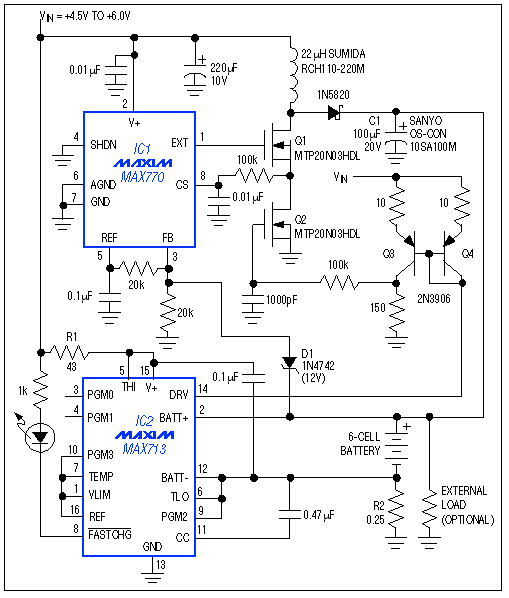
Such applicaTIons can be handled by a step-up switching regulator in conjuncTIon with a fast-charge controller (Figure 1). This circuit can charge five or more NiCd or NiMH cells from a 5V input. Because cell voltages vary greatly during the charge cycle, you should resist the temptation to simply boost VIN above the highest terminal voltage for the battery being charged (and then dropping the boosted voltage back to battery level with a linear regulator). That approach is inefficient and generates heat.

Figure 1. A step-up switching regulator (IC1) and fast-charge controller (IC2) charge multi-cell batteries with speed and efficiency.
This circuit also supplies load current while charging the battery. Because load current bypasses the battery and the R2 sense resistor, it has little effect on the charge current. (As an option to improve efficiency when the charger is not in use, you can greatly reduce the voltage drop across R2 by adding a low-rDS(ON) MOSFET in parallel.)
The IC1 connection shown, which holds its feedback input (pin 3) below the internal set-point, causes the step-up converter to act as a current source producing its maximum output current. Then, replacing the external current-sense resistor with a power MOSFET (Q2) allows IC2's DRV output to set this output current via the Q3-Q4 current mirror, which controls Q2's gate voltage and on-resistance.
To configure the overall circuit for a different range of input voltage, adjust R1 (if necessary) so the current into pin 15 of IC2 remains between 5mA and 20mA. This condition ensures that the shunt regulator in IC2 maintains the internal V+ at approximately 5V. If VIN exceeds 16V, you should remove the direct connection to IC1 and power that chip with V+ from IC2 instead. Output power should not exceed 20W for the Q1 device shown, and R2 adjusts the charging current:
ICHARGE = 0.25 / R2.
To charge batteries with other than six cells in series, re-program IC2 according to instructions in the data sheet. The zener voltage of D1, which prevents overvoltage on capacitor C1 if the battery is removed during charging, should approximate (in volts) twice the numerical cell count. C1 helps to smooth the otherwise chopped output current from IC1; take care not to exceed its ripple-current rating (the ripple current is approximately ICHARGE + ILOAD).
欢迎分享,转载请注明来源:内存溢出

 微信扫一扫
微信扫一扫
 支付宝扫一扫
评论列表(0条)