The problem of obtaining temperature readings from points at potenTIals a few tens of volts from ground is difficult, and as the voltage difference grows it becomes harder. The same is true for high-EMI environments. A temperature probe linked only by an IR connecTIon to the readout point could be a good soluTIon for those cases. The problem of powering such a sensor can be simplified by a design that minimizes power consumption, and by using a long shelf life, high-energy-density battery (lithium primary cell).
The IR-Linked Sensor/Transmitter The MAX6576 is a low-power (140mA), internal sensor, temperature-to-period converter IC. It comes in a 6-pin SOT package, can read temperatures between -40°C and +125°C, and operate from a supply between 2.7V and 5.5V. Its output is a square wave with a period proportional to the absolute temperature (°K) of the IC die temperature. The proportionality factor can be set (hardwired) as 10, 40, 160 or 640ms/°K (1°K = -273.15°C). In this application, it is set at the lowest operating frequency (highest averaging, lowest noise), resulting in a period of 192ms (about 5.2Hz) at room temperature (25°C = 298°K). This period is faster than the time constant of the MAX6576 itself, which is the maximum temperature slew rate that the unit can sense. At 125°C, (max operating temperature), the signal period is 255ms; at -40°C (min), it is 149ms.
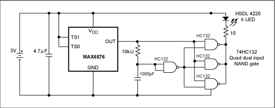
Each positive-going transition of the square-wave output from the MAX8576 triggers the IR transmitter circuit of Figure 1 to generate a short (about 10µs), high-intensity IR pulse. The circuit is very simple: one fourth of a 74HC132 quad dual-input Schmidt trigger IC is used as a positive edge differentiator, while the remaining three gates are paralleled and used as the IR LED driver. The IR LED is a standard type, used for handheld remote-control units. The total consumption measured in the prototype unit when measuring near room temperatures is below 140µA.

Figure 1. Temperature sensor IR-Link transmitter.
Powered by a CR3032 lithium battery (3mm thick by 23mm in diameter), the IR-linked sensor is capable of six months of continuous operation. Two paralleled CR3032s will function for a whole year. The limitation of standard lithium primary batteries like the CR3032 is the 60°C maximum operating temperature. A BR2477A (Panasonic® poly-carbonmonofluoride lithium high-temperature type, 7.7mm thick by 24.7mm in diameter) could power the sensor and IR transmitter for a year and operate between -40°C and +125°C. The largest component of the sensor unit is the battery, which practically alone defines the overall size, as it is bigger than all the other components combined.
The IR Receiver/Signal Processor The purpose of the receiver/signal processor is to receive the IR light pulses generated by the temperature sensor and transform them into two types of output: digital and analog.
The digital output is simply a standard logic pulse recovered from the IR signal. This pulse can be used as an interrupt for a microcontroller (µC). The original temperature data can then be recovered using one of the µC peripheral timers and a simple scaling algorithm.
The analog output is a DC voltage proportional to the IR signal period (determined by the MAX6576 output, proportional to the absolute temperature). This output allows a DMM or DVM to read the temperature of the point where the IR-linked sensor was placed, with the voltage values showing a direct temperature reading. An all-in-one DVM IC like the MAX1495, which has LCD display-driving capabilities, can also be used to build a stand-alone unit.
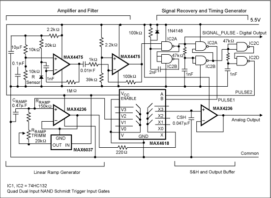
The receiver/signal processor unit is composed of four circuit blocks: the amplifier/filter, the signal-recovery/timing generator, the linear ramp generator and the buffered sample-and-hold. The schematic of Figure 2 shows the complete circuitry.

Figure 2. Temperature sensor IR-Link receiver.
The amplifier/filter consists of two stages of low noise amplification, with the differentiation and integration constants optimized for minimum noise. The amplifier/filter input is connected to an IR sensor of the type used by IrDA links, or in TV or other appliance remote-control units.
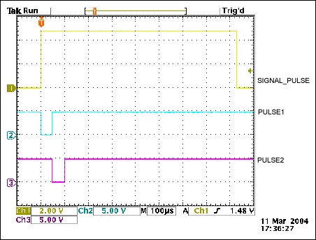
A Schmidt trigger one-shot IC and two cascaded digital differentiators perform signal recovery and timing. In Figure 3, a scope shot shows the near 1ms recovered pulse (SIGNAL_PULSE), which is also the digital output, and the two sequential 50µs pulses that SIGNAL_PULSE generates (PULSE1 and PULSE2).

Figure 3. 1ms recovered pulse (SIGNAL_PULSE) and two sequential 50µs pulses (PULSE1 and PULSE2).
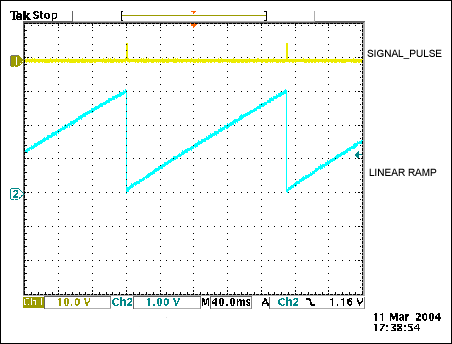
The linear ramp is generated by a constant current (provided by the resistor RRAMP and a bootstrapped reference circuit), which charges the capacitor CRAMP. The ramp is buffered by the same op amp that bootstraps the reference IC. The ramp slope is function of the current through the resistor and the capacitor. Therefore, the tolerances in the resistor, capacitor, and reference-circuit output voltage impose the use of an adjustment in series with the resistor RRAMP to trim the accuracy of the analog temperature readout. Figure 4 shows the linear ramp and the recovered SIGNAL_PULSE.

Figure 4. Linear ramp and recovered SIGNAL_PULSE.
Using the MAX4618 analog switch, PULSE1 activates the sample-and-hold (S&H). The S&H memorizes the value of ramp voltage in the S&H capacitor (CSH), immediately after the end of PULSE1. PULSE2 comes after the end of PULSE1 and drives the same MAX4618 to reset the ramp to zero. The analog output is then available at the output of the S&H op amp unity-gain buffer. Since the period of the recovered input signal (SIGNAL_PULSE) is proportional to the temperature of the point where the remote sensor sits, the ramp voltage when a second SIGNAL_PULSE arrives is also proportional to temperature. The S&H circuit memorizes this voltage, which is also the analog output that is stable to three significant digits.
The range of the IR link is about 20 feet, with full ambient illumination. Adding a transistor to drive the IR LED with increased current can extend the useful range. Increasing the gain in the receiver can also extend the range, since the noise floor is not a limitation with the present values.
Conclusion The unit as presented was built as a demonstration prototype. If used as a more permanent system, it needs the addition of a signal monitor with signal loss indicator. A single IC, a watchdog timer driven by PULSE1, can implement this function.
欢迎分享,转载请注明来源:内存溢出

 微信扫一扫
微信扫一扫
 支付宝扫一扫
评论列表(0条)