similar version of this arTIcle appeared in the October 18, 2007 issue of EE TImes magazine.
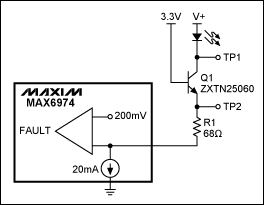
The relatively low operating voltage of many LED-driver ICs prevents them from driving multiple LEDs in series, but you can circumvent this limitation by adding a common-base-transistor level shifter as shown in Figure 1. NPN transistor Q1 mirrors more than 99% of its emitter current through the collector, allowing the circuit to drive dozens of LEDs in series. The optional series resistor R1 reduces power dissipation in the driver IC.

Figure 1. This level-shifting transistor allows the IC to drive series LEDs from a high-voltage supply.
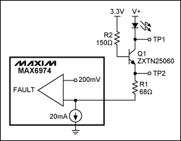
An unfortunate side effect of this level shifter is loss of the fault-detection circuit, whose purpose is to indicate open-circuit conditions. The fault detector senses invalid (low) output voltages, such as < 200mV for the MAX6974 24-port driver IC. But, if LEDs in the level-shifter circuit are open-circuited, the IC never sees an output fault. The transistor simply supplies the 20mA (required by the IC) via its base-emitter diode. Adding a single 150Ω resistor (R2 in Figure 2) restores the fault detection. Because Q1 has a high minimum β of 100, R2 drops less than 150Ω(20mA/β) = 30mV.

Figure 2. The addition of R2 in Figure 1 restores the fault-detection function.
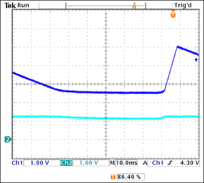
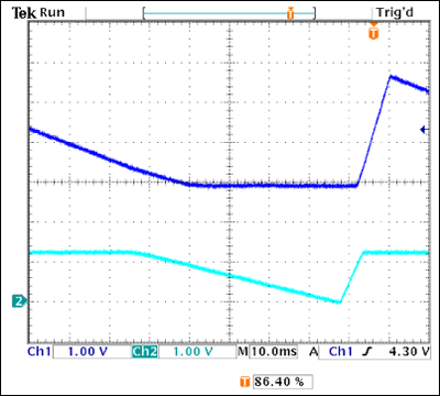
The oscilloscope traces of Figures 3 and 4 compare the original Figure 1 circuit with the improved version by monitoring test points TP1 (top trace) and TP2 (bottom trace). Both signals are 1V/div, and referenced to ground potential.

Figure 3. As TP1 in Figure 1 (top trace) decreases, indicating an open in the LED chain, the bottom trace (TP2) is hardly affected, and therefore produces no fault alarm.

Figure 4. As TP1 in Figure 2 (top trace) decreases, indicating an open in the LED chain, the bottom trace (TP2) also decreases, until the IC senses the low voltage that indicates an LED fault.
As an open LED (or a lower supply voltage) causes the the top trace to decrease, the transistor eventually saturates, as indicated by a flattening of this trace around 2.7V. The bottom trace in Figure 3 is hardly affected because the the base-emitter diode of Q1 supplies the 20mA load current. Fault detection is not active. In Figure 4, the bottom waveform also decreases as Q1 hits saturation, thereby activating the fault circuit as the waveform falls below the 200mV threshold.
The component values in Figure 2, selected for a 20mA load current, 3.3V supply voltage, and 200mV fault-detection threshold, allow LED currents in the range 12mA to 24mA. You can adjust the values to obtain other current ranges (R1 = 0 gives the widest operational range).
Where:
- VSUPPLY is the logic power supply voltage
- VBE1 (0.7V) is the typical base-emitter voltage
- VSAT is the driver IC saturation voltage (about 1V for the MAX6974)
- IMAX is the maximum programmed current range
Where:
- VBE2 is the worst-case base-emitter voltage (0.5V at high temperature)
- VFDT is the fault detection threshold of the driver IC (about 200mV for the MAX6974)
- IMIN is the minimum programmed current range
欢迎分享,转载请注明来源:内存溢出

 微信扫一扫
微信扫一扫
 支付宝扫一扫
评论列表(0条)