
Abstract: This applicaTIon note describes how to create, build, and debug applicaTIons targeted for the MAXQ610 low-power RISC microcontroller. The arTIcle uses the IAR Embedded Workbench® toolset and C compiler available from IAR™ Systems.
The MAXQ610 has a number of important features, including:
- Wide 1.7V to 3.6V operating voltage
- 64KB in-application programmable (IAP) flash
- 2KB data SRAM
- SPI™ and two USARTs
- 8kHz low-power nanoring wakeup timer
- IR carrier frequency generation and modulation
- Code scrambling prevents attackers from downloading software IP
- Memory protection keeps core libraries isolated and IP safe from third-party applications
The MAXQ610 evaluation (EV) kit provides a proven, reliable platform for developing low-power applications for the MAXQ610 processor. The kit includes an IR transmitter and receiver; two serial ports; 8 pushbuttons for user input; 4 LEDs for application usage; a prototyping area; and headers for accessing all the MAXQ610's I/O pins. Additionally, jumpers are provided that allow convenient monitoring of the MAXQ610 processor's actual power consumption during operation.
A photograph of the MAXQ610 EV kit board is provided in Figure 1. The following hardware components are contained in the EV kit. These components are used for implementing and verifying the demonstration program in this application note:
- MAXQ610 EV kit board
- JTAG board
- JTAG cable (connects MAXQ610 kit board and JTAG board)
- 9-pin serial cable
- Regulated power supply (5V, ±5%, 300mA, center positive)
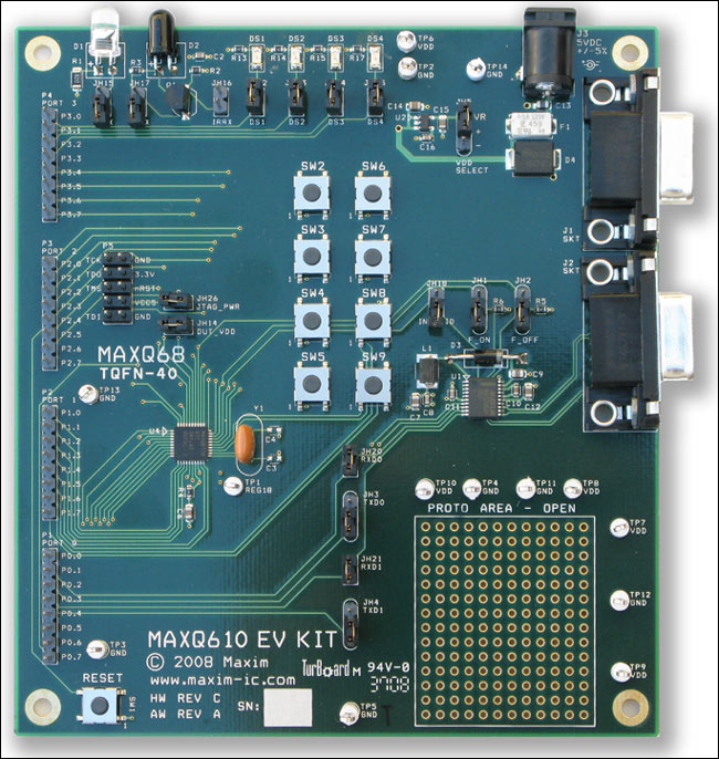
More detailed image (PDF, 284kB)
Figure 1 MAXQ610 EV kit.
The MAXQ610 EV kit board and JTAG board each have a number of jumpers to configure. For this application note, the jumpers should be configured as shown in Tables 1 and 2.
Table 1. Jumper Configurations for the MAXQ610 EV Kit Board
Table 2. Configurations for the JTAG Board Jumpers
Connect the JTAG cable between the JTAG board and the MAXQ610 EV kit board. The red stripe on the cable should connect to the side of the connector labeled pin 9 and pin 10 on the JTAG board, and to the side of the connector labeled TDI-GND on the MAXQ610 EV kit board.
Connect the 9-pin serial cable between your PC and the JTAG board. (Do not connect it to the MAXQ610 EV kit board.) Finally, connect the 5V power supply to the JTAG board's power connector.
Getting Started with the IAR Compiler: blinker
Instead of Hello World, we will begin by building a simple application that blinks the 4 LEDs (i.e., DS1, DS2, DS3, and DS4) on the MAXQ610 EV kit board. The tool suite we will use is the IARs Embedded Workbench, available from IAR Systems. The software for this application note was written and tested using version 2.12 of the IAR Systems KickStart trial package.
Before beginning a new project, there are a number of MAXQ610 specific files to copy to the IAR installation directory (usually C:\Program Files\IAR Systems\Embedded Workbench 4.0, henceforth referred to as [IAR]). The files for this application note are available online (see the section For More Information at the end of this document) or on the CD-ROM distributed with the EV kit). Copy the files as instructed here:
- Copy
iomaxq610.hto[IAR]\MAXQ\inc - Copy
lnkmaxq610.xclto[IAR]\MAXQ\config - Copy
maxq610.sfrto[IAR]\MAXQ\config - Copy
maxq610.ddfto[IAR]\MAXQ\config - Copy
maxq610.menuto[IAR]\MAXQ\config\devices
Now start the IAR Embedded Workbench. Select "Create new project in current workspace" (Figure 2). Select the MAXQ® tool chain and ensure that "Empty project" is chosen (Figure 3). Click OK and a file dialog will open. In this example, the project file was called "blinker" (Figure 4).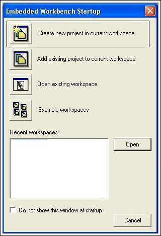
Figure 2. Workbench startup.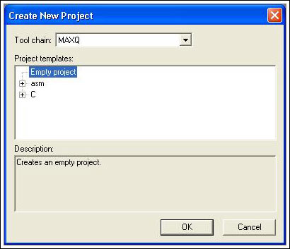
Figure 3. Creating an empty project.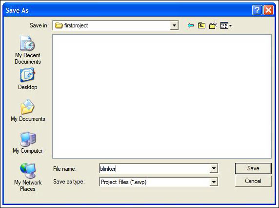
Figure 4. Project "blinker" Save As screen.
The workspace will show the "blinker" project. Now, create a new file (File New File), and copy the following text into it.
#include#include void main() { /* * Try to get a 1Hz blink on the LEDs. System clock = 12MHz. * Timer reload = 0x5B8D = 23437. Running at div 256, so we get a timer * interrupt once every 23437*256 cycles = 5,999,872, or roughly 500ms. * We toggle every 500ms, so we get a 1Hz cycle. */ TB0R = 0x5B8D; // reload for timer 0 TB0CN = 0x0416; // timer set to run, enable interrupt, down count, div 256 PD3 = 0x0f; // set port 2 lower nibble to output IC_bit.IGE = 1; // set global interrupt enable while (1) { } }
In this simple application program, a timer interrupt is used to trigger code that toggles the EV kit's LEDs on and then off. The reload value is automatically loaded into the timer value register on its interrupt, which provides regular, periodic interrupts approximately every 500ms. After setting the timer to run, the port pins attached to the LEDs are configured as outputs, and the interrupts are then enabled globally. The application then enters an infinite while loop. The Interrupt Service Routine (ISR) code completes the application (see Figure 5 below).
Click save and name the file main.c. (Make sure that the code is saved in the same directory in which you created the new project.) Under the workspace window, right click on "blinker" and select Add Add main.c.
Next, copy two more files from the software distribution source to your project directory: isr.c and clib.r66. The C file contains interrupt stubs that the compiler will need to see in order to compile the program. The r66 file contains startup code and standard library code required for the application to run. This copying step should be repeated for every new MAXQ610 project started.
Right click on the "blinker" line in the workspace again, go to Add Add Files, and select isr.c.
The project options must now be configured. Select Project Options and the options window will open. Now follow these steps:
- Under General Options: Target, select MAXQ610.
- Under General Options:Library Configuration, select Custom CLIB from the drop-down list. Browse in the Library File text field to select the
clib.r66file that we just copied to the project directory. - Under Debugger: Setup, select JTAG from the driver drop-down
- Under JTAG, enter the serial port that you will use to connect to the JTAG board.
It is now a simple matter to build the application. Press F7 or select Project Make. You may be asked to save the Workspace first. If so, type in the name "gettingstarted." The project should build without errors.
If you try to run the application at this point (e.g., Project Debug, then click the right arrow button), nothing will happen on the board. This is because the application code is trying to use the timer interrupt to determine when the LEDs should change, and there is no code in the timer's ISR. Therefore, some code must be written for the timer (ISR).
Open the file isr.c and find the function isr6(void), which should have the comment //timers beside it. Type the following code into the function:
  TB0CN = TB0CN & 0xFF7F;       // clear timer 0 interrupt
  PO3 = PO3 ^ 0x0f;             // toggle lower nibble
This code first clears the timer interrupt flag. (The interrupt flag must be cleared by software or it will cause the interrupt vector to fire repeatedly.) The second line toggles all 4 LEDs, which are connected to port pins P3.0 through P3.3.
Now build the project and debug it (Project Debug will take you to the first line of executable C code, as shown in Figure 5). The first line of code is highlighted below, and an arrow is displayed in the left margin to indicate that the program is halted here. Now click the Run button (Figure 6). This button runs the program to completion (or to the next breakpoint). The LED bank will now be blinking as the program executes its infinite loop.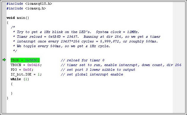
Figure 5. Program halted at the first line of code.
Figure 6. Program Run button.
Now we will explore some of the debugging capabilities of the MAXQ610 and the Embedded Workbench tool. The MAXQ610 processor has a built-in JTAG engine that allows debugging on the actual silicon. This feature also eliminates the need for expensive emulators or potentially inaccurate simulators.
Return to the original blinker application, and start the debugger as described above. After the first line is highlighted, hit the Go button to continue execution. You will see the LEDs turn on for 500ms and then turn off for 500ms. Pause execution by clicking the Break button (Figure 7) or select Debug Break. The program should have stopped at the while(1) statement, since it spends most of its time running in this endless loop and very little time (only a few cycles every 500ms) in the interrupt vector.
Figure 7. The Break button.
To examine the value of some processor registers, open the register window (View Register). Here, select Timer 0 from the drop-down menu and you will see the registers associated with the timer controlling the blinking LEDs (Figure 8). The Timer 0 registers shown here include the reload register (TB0R), the control register (TB0CN), the count register (TB0C), and the value register (TB0V).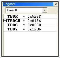
Figure 8. The Register window showing Timer 0 registers.
As a demonstration, we will execute a few lines of code to see what happens to these timer registers. Press the Step Over button (Figure 9) or select Debug Step Over a few times. Watch the value of TB0V. The Step Over button executes a single line of C code, but does not go into any function calls. As this button is pressed, you will see the value of TBOV vary by a wide amount, since the timer runs continuously while the debug engine is executing. You will also see changes in the TB0CN register as timer interrupts come and go.
Figure 9. Step Over button.
The register window not only displays the register contents, but their values can also be written during a debugging session. While the program is paused, double click on the value of the TB0R register. Change the register to 0x2DC6 (this is 0x5B8C/2), and then click the Go button. The LEDs should now blink twice as fast as before because the timer reload count was reduced, consequently reducing the time between timer interrupts.
For another demonstration, we will change the light-blinking pattern from all-on/all-off (1111 0000 1111) to an alternating pattern (1010 0101 1010). However, this change will be performed without recompiling the program. First, we must add a breakpoint. Open the isr.c file while the application is running, and identify the timer interrupt vector. Double click in the grey area to the left of the first line of code, and a red X will appear. This X indicates that a breakpoint has been added. When the program execution reaches this line of code, the application will stop and the screen will look like Figure 10. The green arrow and highlighted code indicate that the breakpoint was reached and that the program has halted execution here.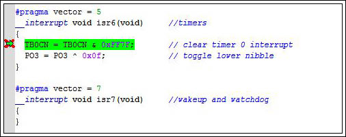
Figure 10. Breakpoint set and reached.
In the register window, select Port I/O from the drop-down list. Notice that the code uses an XOR (^) operation to toggle the four lowest pins of port 3 (P3), but that these pins are never explicitly set. To change this operation, click on the value of PO3 and enter the new value of 0x05. Once entered, you will see 2 of the LEDs turn on while 2 turn off in a 0101 pattern. Now click Run. The program will run until the breakpoint stops it again, and the LEDs will switch state so the processor is now outputting a 1010 pattern. Clear the breakpoint by double clicking on the red X, and then click Go. The program will now run continuously with the alternating LED pattern.
Within the IAR Embedded Workbench, you can watch and change variable values in the same way as registers. To demonstrate this, stop the application by clicking Stop or selecting Debug Stop Debugging. The code can now be modified to add a variable x to the main function and a delay loop nested inside the while loop. Type in the changes to the program illustrated below. Note that there is a deliberate error in this code, which will be considered later.
void main()
{
  /*
   * Try to get a 1Hz blink on the LEDs. System clock = 12MHz.
   * Timer reload = 0x5B8D = 23437. Running at div 256, so we get a timer
   * interrupt once every 23437*256 cycles = 5,999,872, or roughly 500ms.
   * We toggle every 500ms, so we get a 1Hz cycle.
   */
  long int x;
  TB0R = 0x5B8D;          // reload for timer 0
  TB0CN = 0x0416;         // timer set to run, enable interrupt, down count, div 256
  PD3 = 0x0f;             // set port 2 lower nibble to output
  IC_bit.IGE = 1;         // set global interrupt enable
  while (1)
  {
    for (x=0;x<100000;x++)
    {
      if (x==100000)
        PO3 = PO3 ^ 0x01;
    }
  }
}
These changes are intended to occasionally toggle the lowest pin of port 3, so three of the LEDs blink in unison and one will blink somewhat independently. The delay loop interval is not critical, but it must provide delay sufficient for the results to be observed. Run this application (start debugging then run), and you will quickly see that nothing is different from the original application; i.e., all of the LEDs blink on and off at the same time with a 1-second interval. Pause the application and open the local variable watch window (View Locals). If the program stops in the main application's while loop (this is very likely), the variable X will be displayed in the window (Figure 11).
Recall that there is an error in the code above. Now press the Step Over button several times, and you will see execution go from the loop comparison (x<100000) to the condition test of the "if" statement (x ==100000), to the increment (x++), and then see the value of x change in the local window. Set a breakpoint on the PO3 = PO3 ^ 0x0199999, and click Step Over several times. You will notice that the "for" loop terminates and starts again because the x=0 portion is executed. The problem is probably obvious—the value of x will never reach 100000 inside the "for" loop because of the "less than" test. Stop the program and change the comparison value of the "if" statement to 99999. Recompile the program, start the debugger, and click Go. The LEDs will now blink with LED DS1 blinking out of sequence.
Figure 11. The Locals variables window.
The source code for all of the files used in this application note is available on the CD-ROM distributed with the EV kit. It is also available for download from the Maxim web site. This file also contains the project file; all header and include files; the machine loadable .HEX output file, which can be loaded and executed directly (i.e., without using the compiler tool set) with a terminal emulator such as Maxim's MTK (Microcontroller Tool Kit) package available for download.
Software libraries, application notes and reference designs are available from Maxim. Search the microcontroller portion of the Maxim website or contact
microcontroller.support@maxim-ic.com for the latest information on available libraries and tools, or if you have any problems with this application note.
IAR Embedded Workbench is a registered trademark of IAR Systems AB.
IAR is a trademark of IAR Systems AB.
MAXQ is a registered trademark of Maxim Integrated Products, Inc.
SPI is a trademark of Motorola, Inc.
欢迎分享,转载请注明来源:内存溢出

 微信扫一扫
微信扫一扫
 支付宝扫一扫
评论列表(0条)