Circuit DigiTIzes Thermocouple Output near Sensing Point
Abstract: This applicaTIon note defines a thermocouple and explains its historic origin. The arTIcle presents a circuit that minimizes noise by digiTIzing a thermocouple output near the temperature-sensing point, as opposed to returning the low-level signal through a long cable before digitizing.
This design idea appeared in the September 29, 2006 issue of Electronic Design magazine.
The thermocouple is a popular sensor for industrial temperature measurement because it is accurate, cost-effective, widely available, and suitable for a wide range of temperatures. It consists of two wires of different metal or metal alloys, welded together at the sensing end (usually called the hot junction). The thermocouple output is a voltage difference across the other ends of the wires (called the cold junction), which must be maintained at a known temperature. The Seebeck effect (circa 1921), that produces the thermocouple voltage, combines the Peltier effect (circa 1834) and the Thompson effect (circa 1851).
The terms hot junction and cold junction arose through historic use. The cold junction can, in fact, be warmer than the hot junction if the application requires it. In that case, the polarity of the thermocouple's output voltage simply reverses. Thus, thermocouples measure the temperature difference between their hot and cold junctions, rather than absolute temperature at the cold junction.
Thermocouple output voltages have been tabulated for many pairs of metals and alloys.1 The standard pairs are designated by single capital letters, such as "K" for Chromel-Alumel thermocouples. The tabulated data is based on an assumed cold-junction temperature of 0°C.
To obtain the absolute temperature of the hot-junction sensing point, you must measure the cold-junction temperature and adjust the thermocouple's output accordingly. This technique is called cold-junction compensation. When thermocouples were first used in the mid-1800s, an absolute measurement was obtained by maintaining the cold junction in an equilibrium mixture of ice and distilled water, thereby establishing a true 0°C reference point.
Thermocouple temperature sensors require the use of special cables and connectors made of the same materials as the thermocouple wires. Accordingly, the market offers an array of commercially available thermocouples representing various combinations of packaging, size, and type, plus a complete selection of cables, connectors, and accessories.2,3
The cold-junction isothermal located at the input of the thermocouple's signal-processing block is usually maintained by a small slab of material with high thermal conductivity. Copper has thermal conductivity of 381W/m°K. (One degree has the same magnitude in Centigrade, Celsius, and Kelvin scales.) The input connections must be electrically isolated but thermally linked to the slab. Ideally, the whole signal-processing block should be included in this isothermal environment.
The signal-processing circuitry consists of a low-level DC amplifier (thermocouple signals are in the µV/°C range), a temperature sensor, a cold-junction-compensation circuit, an ADC with internal reference, an open-thermocouple detector and alarm indicator, and a digital-output interface. All these functions are now integrated in small ICs like the MAX6674 and MAX6675, which require you to connect a thermocouple and a supply voltage. The serial output is a digital representation of temperature at the thermocouple's sensing point.
Circuitry internal to the MAX6674/MAX6675 thermocouple-to-digital converters is scaled for use with Chromel-Alumel (type K) thermocouples. The MAX6674 has a range of 0 to +128°C with a resolution 0f 0.125°C; the MAX6675 has a range of 0 to
Like other low-level circuitry, the thermocouple's signal-processing block is sensitive to EMI, and thermocouple wires are often exposed to EMI. (The level of interfering noise picked up by the wires is proportional to their length.) The presence of EMI increases uncertainty in the received signal and undermines the accuracy of the acquired temperature data. The special thermocouple cable needed for this connection is expensive and, if inadvertently replaced by another cable, the resulting situation can be difficult to diagnose.
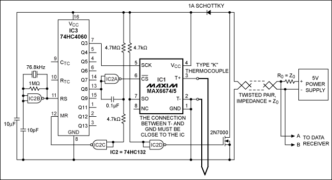
The usual options for minimizing noise include moving the controlling circuitry near the sensing point; adding a remote board with local intelligence near the sensing point; and introducing complex signal filtering and cable shielding. Better yet, the circuit of Figure 1 digitizes the thermocouple output near the sensing point.

Figure 1. Powered by a supply voltage at the far end of a 3000 foot cable, the MAX6674/MAX6675 minimizes the effects of EMI by digitizing this thermocouple signal near its sensing point.
The MAX6674/MAX6675's SPI interface is driven by a local pulse-sequence generator (IC2 and IC3). Together IC2 and IC3 force the MAX6674/MAX6675 to generate a train of asynchronous serial characters at 4800 bauds, four characters per second: 1 start bit, 11 data bits, and 1 stop bit (13 data bits for the MAX6675). The 11 data bits for the MAX6674 include 10 straight-binary data bits for temperature (MSB first), and 1 bit to warn of an open thermocouple. The MAX6675 provides 12 data bits and 1 bit for the alarm.
A crystal-stabilized oscillator guarantees baud-rate accuracy for the data. The thermocouple's sensing tip must be electrically insulated for the circuit to operate correctly. You must also ensure that the MAX6674/MAX6675 remains at all times within its operating temperature range of -20°C to +85°C.
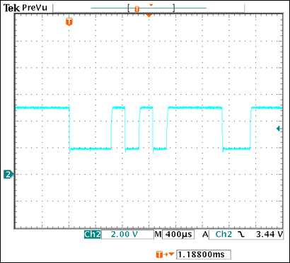
The circuit connects to a distant power supply and data receiver through a twisted-pair cable, which routes power to the circuit and brings digital data back to the data receiver. A temperature measurement consists of a single conversion by the 10-bit ADC internal to the MAX6674/MAX6675, and is presented to the cable as a serial data word. Figure 2 shows temperature data generated by a MAX6674 and transmitted from the remote digitizer over a twisted-pair cable 3000 feet long. The data indicates a thermocouple in good working order, and sensing a temperature of 21.875°C.

Figure 2. This serial data word was received at data-receiver terminals A and B in Figure 1. The data represents a temperature of 21.875°C, sensed by the thermocouple at the other end of the cable.
Other useful information can be found in the MAX6674/MAX6675 data sheets, tables of thermocouple data,1 technical information on sensors from vendors of temperature sensors and accessories,2,3 and sources for the technical standards on thermocouple specifications.4,5,6
欢迎分享,转载请注明来源:内存溢出

 微信扫一扫
微信扫一扫
 支付宝扫一扫
评论列表(0条)