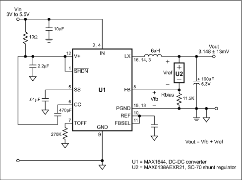
The consequence of this square law dependency is a 2% change in power dissipation for every 1% change in voltage. Clearly, tight power control is a consequence of tight voltage control. To achieve that goal, the circuit of Figure 1 produces an output voltage whose accuracy is far tighter than that of the DC-DC converter's internal voltage, and without need for precision external resistors.

Figure 1. Substituting a shunt regulator (U2) for the customary resistive divider in this DC-DC converter dramatically improves the output voltage accuracy.
To determine the optimum supply voltage, you must consider the circuit's minimum voltage requirement, the DC-DC converter's output ripple and line/load regulation, and any voltage drops between the converter and its load(s). One would ideally set the power-supply output to the resulting minimum, but actual DC-DC converters have non-ideal references whose percent error appears directly in the output. The tolerances on discrete-valued external resistors also contribute an output voltage error. The circuit of Figure 1 (and the modifications shown in Figure 2) describe a technique that almost eliminates the potentially significant errors contributed by a resistive feedback divider. It also minimizes error due to variation in the internal reference voltage.

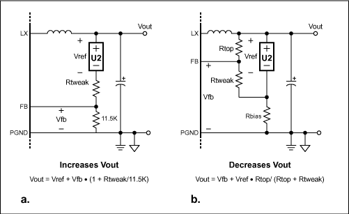
Figure 2. To adjust the output voltage, add Rtweak to the Figure 1 circuit to either increase Vout (a) or decrease Vout (b), as indicated by the equations.
The Figure 1 circuit is that of the MAX1644 Evaluation Kit, except that the output divider has been replaced with bias resistor Rbias and a 0.1%-accurate 2.048V shunt regulator (U2). The DC-DC converter's output voltage is the sum of the shunt voltage and the internal reference voltage at the feedback point. The MAX1644 reference voltage is 1.10V ± 11mV (which is ±1%), and the MAX6138 shunt reference voltage is 2.048V ±2mV. The circuit's output voltage is therefore 3.148V ±13 mV (which is ±0.4%). If we assume that output power varies as the square of the voltage, then it varies by ±0.8%, which is a range of 1.6%.
Note that the output-voltage accuracy (±0.4%) is better than the DC-DC converter's reference-voltage accuracy (±1%). That result cannot be achieved with a resistor string, even one with perfect resistors, nor can it be achieved even with the output tied directly to the internal reference.
An output of 3.148V -0.4% is almost exactly 3.3V -5%, which may be optimum for many 3.3V systems. For other values of output voltage, consider Figures 2a and 2b. Figure 2a adds a resistor (Rtweak) in series with the shunt reference, thereby raising the output voltage by an amount VFB × Rtweak/11.5kΩ. If Rtweak is small it will have a negligible effect on output voltage accuracy. If the output voltage is too high, you can lower it using the circuit of Figure 2b. Here again, small values of Rtweak will have a negligible effect on output voltage accuracy. Note that the Rbias value should be small enough to provide for U2 a minimum bias current of 65µA.
To compare the output accuracy of Figure 1 with that of a 3.148V DC-DC converter featuring a simple resistive divider in the feedback path (Table 1), consider a 143k/76.8k divider using 1% resistors. Assuming a 1.1V reference in the converter IC, the worst-case variation in output voltage due to the resistor tolerance is approximately ±1.3%. Any variation in the reference (±1%, in this case) is seen directly in the output voltage. Thus, adding the two independent sources of error (±1.3% and ±1%) yields an output-voltage variation of ±2.3%, producing a power variation of ±4.6% (a range of 9.2%).
Table 1 3.148V DC-DC converter featuring 1% resistor divider vs. 0.1% shunt
欢迎分享,转载请注明来源:内存溢出
赞
(0)
打赏
 微信扫一扫
微信扫一扫
 支付宝扫一扫
 微信扫一扫
微信扫一扫
 支付宝扫一扫
Miniature, Precision Negative
上一篇
2022-08-04
Selecting the Right Series Vol
下一篇
2022-08-04

评论列表(0条)