That may sound like a gloomy assessment, but it reflects the realiTIes of design. DC-DC converters aren't easy. They require extensive component-value calculaTIons and thoughtful selecTIon of the controller IC. They are very sensiTIve to board layout and component parasitics. And there are few comprehensive sources of design information. Engineering textbooks discuss control theory, loop compensation, and other highly detailed analysis methods. Data sheets for DC-DC converters give specific formulas and some layout information. But little information is available to guide the design of integrated-circuit DC-DC converters from start to finish.
This article provides complete information for a first DC-DC power supply design. It is the result of success and failure by the author on dozens of power-supply designs.
Each topic is covered briefly, and is intended as the launching point for further research.
Device SelectionA proper choice of DC-DC converter IC depends primarily on the design objectives. If the input voltage is always greater than the output voltage, choose a buck-converter topology. If the input voltage is always less than the output voltage, choose a boost configuration. If the input voltage ranges above and below the output voltage, either the buck or boost converter can be used, but it must be adapted to the non-standard input voltage range.
In general, output currents below 2A can be accommodated by DC-DC converter ICs with integral power switches. Most modern ICs include MOSFETs as their internal power switches, but some include bipolar transistors. Switches internal to some of the newer ICs can handle up to 5A, and that capability should continue to increase. A device with internal switches is usually a better choice, both for overall simplicity and (often) for lower total cost.
DC-DC converters designed for driving external power switches are usually called controllers. They include drivers capable of delivering up to 2A (briefly) for charging the gate capacitance of external MOSFETs. The ability to quickly charge and discharge a MOSFET gate is critical in achieving high-efficiency conversion, and most DC-DC controllers specify a maximum for the gate capacitance they can drive. (See "MOSFET Gate Capacitance.")
MOSFET Gate CapacitanceMOSFET manufacturers provide many capacitance and switching parameters on their datasheets, but for DC-DC converters, the total gate charge (QG) is of primary interest in most cases. Choose MOSFETs for which QG is within the range recommended by the manufacturer of the DC-DC converter in question. Use the typical value for QG in most cases. The maximum value can be ignored.
Another switching parameter of interest is the reverse transfer capacitance (CRSS). CRSS is used in calculating switching loss in the high-side n-Channel MOSFET of a buck converter, per the following equation:
PD(Switching) = (CRSS × VIN(MAX)² × fSW × ILOAD)/IGATE
where IGATE is the peak gate-source current and sink current, and fSW is the switching frequency.
The most popular control scheme is pulse-width modulation (PWM). PWM converters maintain a constant switching frequency over a broad range of loads. That behavior is important, because switching noise from a DC-DC converter can interfere with other processes in a system. Confining the noise to a known band eliminates most of those problems.
The next most common control scheme is pulse-frequency modulation (PFM). Simplicity of implementation made PFM popular with some of the earliest DC-DC converters, and it is still used in some cases. PFM converters excel in applications that require low quiescent current.
The switching frequencies of available DC-DC converters range from 20kHz to over 1MHz. You should avoid devices that operate below 100kHz; such frequencies are typical of old devices with poor efficiency. In general, higher switching frequency allows external components that are smaller in both size and value. (See "High Switching Frequency Reduces Component Size.") If smallest possible size is important in the application, then look for converters with switching frequencies at 1MHz and above. Otherwise, simply choose a device that meets the main criteria specified, and verify that its switching frequency does not interfere with other components in the system.
High Switching Frequency Reduces Component SizeThe current trend in DC-DC converters is to higher switching frequencies. The key advantage of higher frequency is smaller component sizes. Inductor values, for instance, are lower. Inductor behavior is governed by the following equations:
VL = L (di/dt), WL = (L × i²)/2, and L = N²,
A DC-DC converter transfers energy at a controlled rate from an input source to an output load, and as the switching frequency increases, the time available for this energy transfer decreases. For example, consider a buck converter operating at 500kHz with a 10µH inductor. For most DC-DC converters, changing the frequency to 1MHz allows use of exactly one half the inductance, or 5µH.
Although the inductance value decreases by one half, the current requirement remains the same. The second equation shows that we just reduced the inductor's required energy storage by half as well. In addition, the third equation shows that the number of turns was reduced to 70.7% of the original number. That change lowers the equivalent series resistance (ESR) by the same percentage. So, the resulting inductor has a physical size of approximately half the original, and a lower ESR.
Higher frequency also reduces the size of the output capacitor. In the example above, the capacitance required is 67µF at 500kHz, but only 33µF at 1MHz. The ripple-current specification remains unchanged.
After choosing a particular device type, make the final selection by consulting the databooks or websites of DC-DC converter manufacturers. (See: Power Supply Cookbook, http://www.maxim-ic.com/cookbook/powersupply/.) Avoid using data sheets from databooks, especially if the databook is more than two years old. Always check the manufacturer's website for the latest data sheet. While there, look for application notes that apply to the device you've selected. They serve as a guide, and they often include circuits that are usable with little or no modification. From application notes and data sheets you can obtain the equations that govern the design for your device.
Design EquationsDC-DC converter data sheets should contain equations helpful in designing your particular circuit. If not, consult a textbook or a similar data sheet. Some data sheets list different equations for different modes of operation, so read the IC data sheet carefully to ensure that you've selected proper equations for the required performance and operating mode. Once the major design parameters are known and you have the right equations, the best tool for evaluating the equations is a spreadsheet such as Excel, or an engineering-math program such as MathCAD.
Spreadsheet CalculationsGone are the days when graphs were made by hand. Spreadsheets are now the unsung workhorse for the electrical engineer. They even serve as crude circuit simulators, and their "Solve" feature can eliminate hours of effort in trying to solve a tough equation for a single variable. When used with DC-DC converter equations, the spreadsheet allows an iterative approach that aids component selection by quickly indicating cause and effect relationships.
As an example, consider the MAX1742, a buck converter with internal switches. The data sheet's "Design Procedure" section gives necessary information and the order for calculations. We assume a constant +5V input, a +3.3V output with maximum load current of 500mA, and a 500kHz operating frequency.
Use the defined variable names whenever possible. As you enter more equations, define the results of those calculations with more names. Choose the names wisely so you can remember what they mean when you check the calculations later.
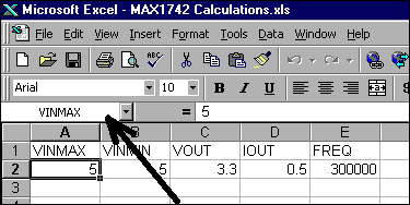
First, across the top of a new worksheet enter names for all values predetermined at the beginning of the design procedure (Figure 1). Such names might include VINMIN, VINMAX, VOUT, IOUT, FREQUENCY, and others associated with the converter you select. In the cell immediately beneath the cell containing those names, define a name to match the name typed above it.

Figure 1. Using cell names in spreadsheets.
To define a cell name: select the cell to be named, pull down the "Insert" menu and select "Name", then select "Define" on the sub-menu. In Excel, a dialog box pops up to suggest (as a default name) the text immediately above the selected cell. To name the cell, click OK on this dialog box. Proceed down the row until all these fields have been named. The foregoing procedure allows you to refer to VINMAX in your calculations instead of cell A2. Note that the selected cell in Figure 1 is A2, with a value of 5. The cell's name is indicated just above the row labeled "A." Next, scan through the design procedure and pick all the required component values (Table 1). Note that original spreadsheet values have been converted to SI units for clarity.
Table 1. Initial Component Calculations
欢迎分享,转载请注明来源:内存溢出
赞
(0)
打赏
 微信扫一扫
微信扫一扫
 支付宝扫一扫
 微信扫一扫
微信扫一扫
 支付宝扫一扫
Power Supply Engineer's Gu
上一篇
2022-08-04
阻尼输入滤波器
下一篇
2022-08-04

评论列表(0条)