What Is PEC and How Does It Work?The DS1862 features a packet-error checking (PEC) mode (PEC enable, 76h, bit 0, = 1) that is useful to improve the reliability of the communication bus by detecting bit errors. By enabling PEC, extra information is included in the data string during each read and/or write sequence. This extra information includes the number of bytes (to be read/written), CAB (CRC add-on-byte), and the CRC-8 byte (check-sum). The differences between normal I²C‡ and PEC communication are detailed below.
Reading with PECDuring read operations, the communication sequence includes bytes for chip address, memory address, number of bytes to be read, a repeated chip address, 1 to 128 bytes of data, and the CRC-8. It is important to note that not all of these bytes will be included in the calculation of CRC-8. The included bytes are memory address, the number of bytes to be read, and all the data (1 to 128 bytes). Once the final CRC-8 byte has been transmitted, it can be compared with the host's calculated CRC-8. If they match, the host will signal with an ACK; if not, a NACK and a reread must occur.
Writing with PECDuring write operations, the communication sequence includes bytes for chip address, memory address, number of bytes to be read, 1 to 4 bytes of data, a CRC-add-on (CAB), and the CRC-8. The CAB byte can be written to 00h, and is intended to delay the communication sequence to allow the DS1862 time to calculate the CRC-8. As with reads, it is also important to note that not all of these bytes will be included in the calculation of CRC-8. Included bytes are memory address, the number of bytes to be read, and the data (1 to 4 bytes). Once the final byte (CRC-8) has been transmitted, the DS1862 compares it with its own internally calculated CRC-8. If they match, the DS1862 will signal with an ACK, if not, a NACK and a rewrite must occur.
Two Methods for Calculating CRC: Speed vs. ExpenseFor the host to compare CRC-8 values, it must first calculate the CRC-8 value. Typically, an algorithm is incorporated into the host's software (or firmware) to solve this problem. Because the DS1862's I²C communication can operate at speeds of 400kHz, a CRC must be calculated quickly. Depending on the host processor's speed (instructions per second) and the availability of extra memory (EEPROM) that can be used for a lookup table, one of two CRC-8 calculation methods is possible: direct calculation of the CRC-8 or calculation of the CRC-8 by indexing a lookup table.
Direct calculation of the CRC-8 typically takes longer than the lookup table method because it must "grind" through every data bit within the data string until the whole string is processed. The advantage to this method, however, is that it is relatively straightforward to understand and does not require much overhead in memory resources (EEPROM for lookup tables). Depending on the throughput of the host processor, direct calculation of the CRC-8 might or might not be an option. If a CRC-8 value cannot be calculated and/or compared in a reasonable amount of time, then the lookup table method can be the best option.
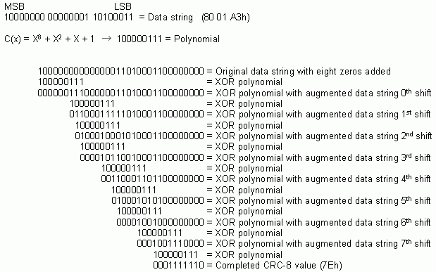
Direct-Calculation MethodThe DS1862 uses a CRC polynomial of type C(x) = X8 + X² + X + 1. The width of the polynomial is 8 (hence CRC-8) and can be represented as 1 0000 0111b. To implement software code for calculating the CRC-8 directly, a simple procedure can be established and programmed accordingly:
- Concatenate the end of the data string (LSB) with eight zeros.
- Perform the XOR operation on the data string against the binary version of the polynomial.
- First, shift the data string until a "1" appears at the MSB of the register.
- Line up the first "1" of the polynomial (1X8 part) so that it will logically operate against the first "1" of the data string when the XOR is performed.
- Perform the logical XOR of the 8 bits. There are actually 9 bits being operated on, but the first "1" bit will always result in a "0." This "0" is in the MSB place, and thus does not contribute to the magnitude of the final CRC value.
- The result of the XOR operation should then be augmented by the "untouched" bits (those bits in the data string that are nine places to the right of the first "1" in the string). This augmented result is now saved in place of the data string.
- Continue the process of shifting and XORing (from step 2) until the LSB of the polynomial does not line up with any of the added eight zeros (the end of the data string with eight zeros added has been shifted sufficiently so that all bits have been operated on). The result will be a completed CRC-8.
Calculation Method

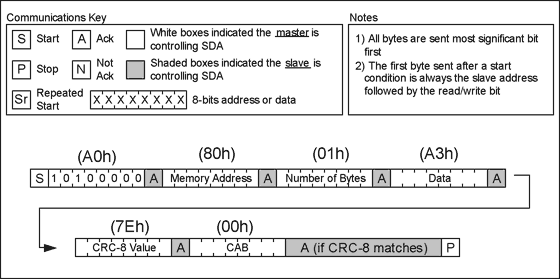
Therefore, a complete write sequence to the DS1862 would look like the following (Figure 1):

Figure 1. A write operation with PEC enabled.
Table-Driven MethodSome host systems might not be able to directly calculate the CRC-8 in a reasonable amount of time. This is especially likely if the worst-case communication string is read: a long string with 128 data bytes. In this case, a table-driven method can be used to speed up the process. The table method is more efficient because it effectively processes a number of bits at a time. Consequently, the larger the table, the faster the CRC is calculated. Because the DS1862 communicates eight bits at a time, the most reasonable choice is to use a 256-location table capable of processing one byte at a time.
To use this method, a static 256-byte lookup table must first be available in memory and preloaded with the CRC values. Then during the calculation, the table has to be indexed and the result returned. A text file containing the 256-byte lookup table is available.
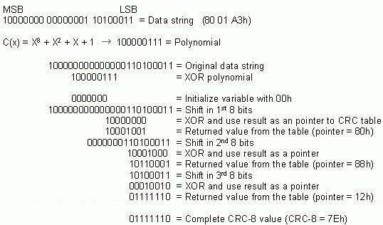
The procedure follows:
- Initialize Register (variable) with zeros.
- Perform the XOR operation on the data string, eight bits at a time.
- XOR 8 bits of the data string with the contents of Register (variable)
- The 8-bit result of the XOR operation is now used as a pointer into the 256-byte lookup table.
- Return the correct table entry.
- Continue the XOR operation on the 8-bit result of the lookup table query against the remaining bytes in the data string, one byte at a time, until the end of data string is reached.
- The last value in the (variable) register is the CRC-8.
Calculation Method

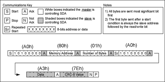
Therefore, a complete read sequence from the DS1862 would look like Figure 2:

Figure 2. A read operation with PEC enabled.
To further illustrate the programming for the table-driven method, actual C code is provided below:
	unsigned char addressbyte, databyte;
	unsigned char CRCbyte, CRCresult;		// Required for PEC transactions

	// Read 2 bytes from the specified memory address from the device at slave address
	Start();
	WriteSlave(SlaveAddress & 0xFE);		// R/W bit = 0
	WriteSlave(addressbyte);			// Starting memory addr to read
	WriteSlave(0x01);				// Read 1 byte
	Start();					// Repeated start
	WriteSlave(SlaveAddress | 0x01);		// R/W bit = 1
	ReadSlave(databyte,ACK);			// Read first data byte and ACK
	ReadSlave(CRCbyte,NACK);			// Read CRC from DS1862 and NACK
	Stop();

	// Calculate CRC - addressbyte, no. of bytes, databyte
	CRCresult = 0x00;
	CRCresult = CRC8LookUpTable(CRCresult ^ addressbyte);
	CRCresult = CRC8LookUpTable(CRCresult ^ 0x01);
	CRCresult = CRC8LookUpTable(CRCresult ^ databyte);


	// Verify CRC is correct
	if (CRCresult == CRCbyte)
	{  // CRCs match }
	else
	{  // Error - CRCs do not match! }
ConclusionThis application note provides a brief, yet functional understanding of packet-error checking (PEC) as it applies to the DS1862 laser-control and digital-diagnostics IC. The calculation and table-driven methods for calculating the CRC-8 are presented with examples, and are a helpful, insightful guide for calculating the CRC-8 and performing reads and writes.If you have questions, comments, and suggestions about this application note, please contact us at:
欢迎分享,转载请注明来源:内存溢出

 微信扫一扫
微信扫一扫
 支付宝扫一扫
评论列表(0条)