The DS1867 is the nonvolatile version of the popular DS1267 Dual Digital Potentiometer. The device provides a drop-in replacement for the DS1267 in applications requiring nonvolatile wiper storage during power-off conditions. Design of the DS1867 uses EEPROM memory array cells for storage of the wipers of the device when power is not applied.
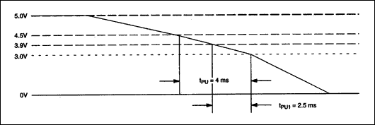
Storage of the wipers is accomplished during a predefined power-down sequence for the supply voltage, VCC. Power-down timing is provided in Figure 1 for this sequence. As shown, the required supply voltage must ramp downward. The DS1867 will initiate wiper storage, as the supply voltage crosses 4.5 volts. Complete and correct storage of the wiper will occur if a time, tPU, of 4ms is maintained for the downward ramp between the 4.5-volt mark and 3 volts or if a 2.5ms minimum time, tPU1, from 3.9 volts to 3.0 volts is achieved.

Figure 1. Power-down timing requirements.
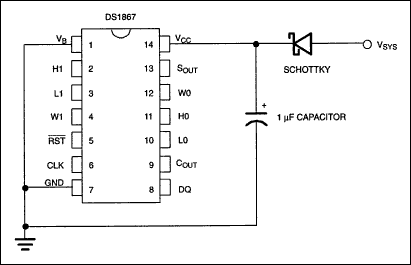
In many cases, the system supply will meet or exceed the power-down requirements for the DS1867 to perform wiper storage. However, if not, then implementing a power supply that will meet the powerdown requirements for storage of the wipers can be achieved by using the circuit of Figure 2. In this circuit, two external components are required. These include a 1 µF capacitor and a Schottky diode (1N5818,1N5819, or equivalent). The 1 µF capacitor is used to provide enough power to the DS1867 during power-down to insure proper wiper storage. The Schottky diode is used to isolate the storage capacitor from the remainder of the system, ensuring all capacitor charge is directed to the DS1867.

Figure 2. Power supply circuit configuration.
Because the Schottky diode has a 0.2-volt drop, care should be taken to insure the voltage (VCC) supplied to the DS1867 is at least 4.5 volts. This requires system power, VSYS, to be 4.7 volts or higher to guarantee proper operation of the DS1867. The substrate bias voltage, VB of the DS1867 should be connected to the lowest required voltage (not to exceed -5V) or ground.
Complete specifications on operation of the DS1867 Dual Digital Nonvolatile Potentiometer can be found in its data sheet.
欢迎分享,转载请注明来源:内存溢出

 微信扫一扫
微信扫一扫
 支付宝扫一扫
评论列表(0条)