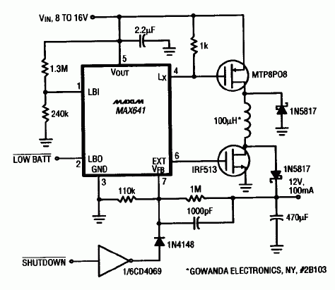
You can't derive a regulated 12V output from a 12V lead-acid battery by using a simple boost converter because it it can't accept an input voltage that is greater than its output voltage. Conversly, a buck converter is a combinaTIon of buck and boost circuitry that successfully addresses the challenge of the wide input-voltage swing associated with the seales lead-acid battery.
The circuit of the MAX641 is a buck/boost converter that provides 100mA at 12V and accepts 8V to 16V inputs. Both ends of the circuit's inductor are switched by separate power MOSFETs, which the MAX641 drives directly via ist LX and EXT outputs. These outputs operate out of phase, the the p- and n-channel FETs turn on at the same TIme. When both n- and p-channel FETs turn off, the two Schottky diodes steer the coil's discharge current to the 12V output. A slight drawback of this circuit is that the converter's efficiency is less that that of a pure busk or boost converter, becuase the two MOSFETs and two diodes increase losses in the charge and discharge current paths. Nevertheless, the circuit sTIll delivers 100mA at a respectable 70% efficiency figure.
An additional benefit of this type of circuit is that you can control its operation with a TTL-level signal. Overriding the VFB input with a high-level TTL signal (such as the diode-coupled inverter output shown) fools the MAX641's internal feedback cicuitry into thinking that the output is too high, so the chip turns off both MOSFETs. The circuit's idle current is around 400µA.

欢迎分享,转载请注明来源:内存溢出

 微信扫一扫
微信扫一扫
 支付宝扫一扫
评论列表(0条)