The proliferaTIon of portable devices in recent years has underlined the need for small, efficient batteries and battery chargers. As a result, there have been great strides in battery technology, with lithium-ion and lithium-polymer among the more popular battery chemistries. To get the most performance from such batteries, designers have focused on the battery charger. In turn, chargers are keeping pace with battery technology, enabling the fullest use of a battery's capacity.
For notebook computers, in which size, weight, and battery life are criTIcal, the standard battery is a lithium-ion type. A recent offshoot of the lithium-ion chemistry uses polymers, which allow the battery to be molded into complex shapes. Lithium-polymer batteries should prove popular for cell phones, handheld computers, and other small applicaTIons. Because lithium-ion and lithium-polymer chemistries are similar, their charging methods are nearly idenTIcal. They differ mainly in their termination voltage and charging current.
The traditional method of charging lithium-ion batteries is to apply constant current and constant voltage. Constant current is applied at the beginning of a typical full-charge cycle, when the battery voltage is low. When the battery voltage rises to a specified limit, the charger switches to constant voltage and continues in that mode until the charging current declines to nearly zero. At that time, the battery is fully charged. During the constant-voltage phase, current drops exponentially due to the sum of battery resistance and any resistance in series with the battery (much like charging a capacitor through a resistor). Because current drops exponentially, a complete, full charge takes a long time.
The limit for charging current need not be as accurate as the limit for charging voltage. The voltage limit is critical: Higher voltage enables the battery to store more energy, but excessive voltage damages the battery. Thus, typical lithium-ion chargers impose the voltage limit with accuracies better than 1%.
Even when charging at a constant high current (higher than ˜1C, where C is the battery capacity in ampere-hours), the constant-current charging time is small compared to the overall charging time. Constant-voltage mode, determined mostly by the battery's physical characteristics, takes most of the charging time. Thus, increasing the charging current has little effect on the overall charge time.
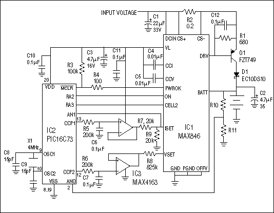
One way of charging lithium-ion batteries is with a linear charger (Figure 1), in which the source for charging voltage or current is usually the DC output of an AC adapter (wall cube). The controller (IC1) drives an external pnp transistor to generate the charging voltage and current. A PIC controller in this circuit (IC2) controls the charging voltage and current via its PWM outputs. By changing the charging voltage and current, this controller accommodates different battery types and chemistries.

Figure 1. A switch-mode charger (IC1) and microcontroller (IC2) form a chemistry-independent battery charger.
In many systems, the extra PWM outputs on an existing controller can program the charger. And, if the charger is dedicated to a single battery type, it can be simplified further by programming the charging voltage and current with external resistors.
Linear chargers are relatively small and simple, but their power dissipation is a drawback. Consider the following: The voltage of a typical lithium-ion battery ranges from 2.7V to 4.2V. To ensure sufficient input voltage to charge the battery to 4.2V, the source voltage must exceed 4.5V. Thus, the output from a typical inexpensive AC wall cube with 10% output-voltage tolerance must range from 4.5V to 5.5V. Maximum dissipation in the pnp pass transistor occurs at maximum input voltage and minimum battery voltage. For a typical 1A ±10% charging current, therefore, the charger's power dissipation can exceed 3 watts.
If this 3W is dissipated in a small portable device such as a cell phone or PDA, the resulting temperature rise can be considerable. It can affect the device electronics, and it may be simply undesirable to the end user. You can reduce the power dissipation with an external battery charger or docking cradle, but these options may not be available. In that case, a switch-mode charger offers the efficiency needed.

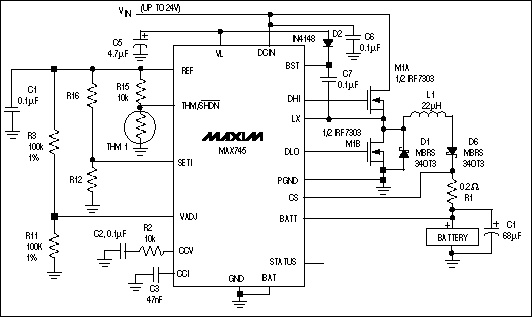
Figure 2. This switch-mode-charger IC exhibits high efficiency over a wide range of source voltage, battery voltage, and charging current.
The IC in Figure 2 uses two external n-channel MOSFETs to chop the source voltage, which is then filtered to generate the required battery-charging current or voltage. These MOSFET pass elements act as switches. They are either on, passing the current with little voltage drop, or off, dropping the voltage with no current. This action greatly reduces power dissipation in the pass transistors (versus that in a linear charger), and the power dissipation shows little variation in response to changes in the source voltage, the battery voltage, and the charging current.
The efficiency of this circuit (>90% over most of its operating range) produces less power dissipation over the wide ranges of source voltage, battery voltage, and charging current. Switch-mode chargers minimize power dissipation at the cost of greater size and complexity.
A new method for charging lithium-ion batteries (constant-current pulse charging) provides the benefits of a linear charger and a switch-mode charger as well. It limits the charging current by employing a current-limited wall cube. The wall-cube current is switched to the battery for constant-current charging. As battery voltage rises to the voltage limit, the current source is switched on and off, thereby supplying a required average current to the battery without exceeding the battery voltage.
Power dissipation is low, because the switch is either on or off, as for a switch-mode charger. Yet the circuit is simple, as is a linear charger, because no output filter is required. It can dissipate more power while in the current-limit mode (depending on the wall cube used), but that has little effect on the battery or its load if the maximum safe temperature is not exceeded.
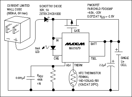
The p-channel MOSFET in a current-limited wall-cube charger circuit (Figure 3) switches the wall-cube current into the battery. Because the IC resides in a small µMax package and the external MOSFET package can be as small as a SOT-23, this circuit is smaller and less complex than a switching charger. A complete charger can be made with only two capacitors and one resistor in addition to the external MOSFET. (RADJ, the LED, the Schottky, and the thermistor are all optional components.)

Figure 3. This lithium-ion-charger IC has low power dissipation, yet requires less space than do typical linear chargers for the same application.
As portable devices become smaller and more complex, the charger becomes more critical in getting the most from the battery. Getting power dissipation out of the device and away from the battery improves the device and reduces stress on the battery. Although conventional linear and switch-mode lithium-ion chargers still have a place, the current-limited source-pulse charger optimizes the size and the performance of portable devices.
欢迎分享,转载请注明来源:内存溢出

 微信扫一扫
微信扫一扫
 支付宝扫一扫
评论列表(0条)