The Swiss start-up company Shockfish SA designed a contact manager for conferences with more than 1000 parTIcipants. Spotme is a small (125mm x 69mm x 14mm) device that looks like a PDA (pocket organizer). It stores photos and relevant data of all conference parTIcipants. A parTIcipant can mark the people he wants to meet. As soon as a marked person is within a 10m radius, the Spotme alerts the user by vibraTIng and the photo pops up on the display.
With the Spotme system, every participant has an up-to-date list of all people attending the conference. As new people arrive, a photo is taken and transmitted to all devices within seconds. The base-station also transmits changes in the conference schedule.
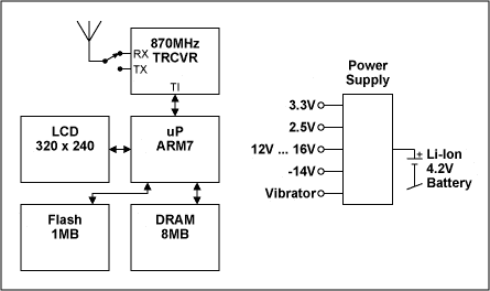
This application note describes some of the ways the company met the power supply design challenges of designing a handheld, battery powered device with graphic display and two-way wireless communications. The CircuitFigure 1 shows the block-diagram of the Spotme wireless communicator. The system uses an ARM7-processor, the display has 16 grey-scales and a resolution of 320 x 240 pixels, and the memory consists of 1MB Flash and 8MB DRAM. The 868MHz ISM-band transceiver is integrated into a chip which contains all RF-blocks.

Figure 1. Spotme, block-diagram.
The whole circuit is mounted on a 6-layer PCB (75mm × 60mm). The Power Supply ConceptShockfish chose a Li+ rechargeable battery as power supply for the Spotme. The device can run for 4-7 days on one charge. Today's processors have usually low supply voltages and require step-down converters. The need for long battery life demands good power supply efficiency.
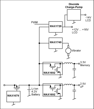
The communicator requires several voltages:
- 2.5V for the processor
- 3.3V for the memory
- 12V-16V adjustable for the LCD
- -14V for the LCD
The MAX1729 is an adjustable step-up converter with temperature-sensor and low quiescent current. The MAX1729 generates the adjustable LCD-voltage of +12V to +16V. A discrete charge-pump inverts this voltage to -14V.
The vibrator-driver MAX1749 ensures a constant force independent of battery voltage.

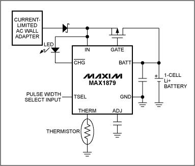
For new designs, the MAX1879 is recommended. The features of the MAX1879 are:
- Continuous voltage- and temperature-monitor
- Charge-time limit
- Charge-cycle is terminated in case of no input voltage (to avoid battery discharge)
- Few external components, no inductor needed (see Figure 3)

Figure 3. Li+ charger with the MAX1879. PWM vs PFM ModeThe MAX1692 used in the Spotme operates either in PWM (pulse width modulation) or PFM (pulse frequency modulation) mode. The designer can therefore choose the mode according to the application requirements.
What are the tradeoffs?
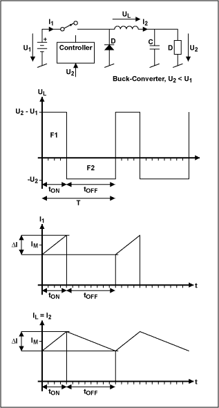
A DC-DC-converter has five main components (see Figure 4, step-down converter):
- switch (MOS-FET)
- schottky-diode (which might be replaced by a second MOS-FET, see Figure 2 with the MAX1692)
- inductor
- capacitor
- controller

Figure 4. Step-down DC-DC converter.
There are two possibilities to keep the output voltage in regulation: The controller can either have a constant frequency and adjust the duty-cycle (PWM) or he can vary the frequency (PFM).
The advantage of the PFM mode is the low quiescent current. This leads to good efficiency for small load currents.
For the PWM converter, the ripple is usually smaller and easier to filter. The higher the switching frequency, the smaller the components (L, C) of the filter. Another advantage of the PWM-converter is that interference is limited to the harmonics of the switching frequency, where for a PFM-circuit the designer has to expect interference over a wider frequency range.
If several output voltages are required and therefore various converters are needed it is a good idea to synchronize all converters to the same frequency. Otherwise disturbing beat frequencies might be generated.
The MAX1692 can operate either always in PWM-mode (for noise-sensitive applications) or it can automatically switch to PFM-mode for smaller output currents.
Depending on the actual application, there might be good reasons to use a PFM or a PWM converter. For devices with a low-power stand-by mode, a PFM-circuit will have the best efficiency. For devices with low-level analog signal-processing (sensor signal conditioning, receivers, audio circuits) it is important to keep the switching frequency out of the signal frequency band. The higher the switching frequency, the easier it is to build an effective filter.
A similar version of this article appeared in the December 1999 issue of Megalinkmagazine.
欢迎分享,转载请注明来源:内存溢出

 微信扫一扫
微信扫一扫
 支付宝扫一扫
评论列表(0条)