
The previous issue of Maxim's Engineering Journal (Vol. 27) discussed new developments in stand-alone battery chargers. This second arTIcle of a two-part series explores the system-level issues in applying battery-charger ICs.
Over the past five years, market pressures on portable equipment have transformed the simple battery charger into a sophisticated switch-mode device capable of charging an advanced battery in 30 minutes. This development also marks a departure from the self-contained, stand-alone charger ICs of only a few years ago. Some of those ICs included considerable intelligence: enough to handle the complex task of fast charging advanced batteries.
Maxim still manufactures stand-alone charger ICs, but market demand has changed recently. Today's battery-charger subsystems regulate charging voltage and current using the intelligence of an external microcontroller (µC), usually available elsewhere in the system. This approach achieves low cost in high-volume applications and allows the greatest flexibility in tailoring the charger to a specific application.
All necessary intelligence once resided in the battery-charger controller IC itself, but now the system designer must implement a charging algorithm and write the associated firmware. This article provides the information and background necessary to implement charger systems based on Maxim's wide range of battery-charger ICs for all popular chemistries.
The following discussion presents an overview of the requirements for charging common battery chemistries with Maxim battery-charger ICs. It addresses system-level trade-offs and firmware design tips, and lists World Wide Web resources available to designers. The discussion closes with design examples based on two common µCs: the 8051 and the Microchip PIC. Either example can serve as a base for further development of custom charger circuitry. Overview of Battery-Charging TechniquesFour rechargeable battery chemistries are in practical use today: Nickel Cadmium (NiCd), Nickel Metal Hydride (NiMH), Gelled Lead-Acid (PbSO4), and Lithium-Ion (Li+). The trade-offs to be made among these chemistries are beyond the scope of this article, but the References section provides access to such information.
Caution: consult the battery manufacturer for specific recommendations. The information presented here is intended only as an overview of charging requirements for various cell chemistries.
This section describes general charging techniques and limitations for the four common chemistries. For additional details and background, see the Maxim data sheets and other reference material cited at the end of the article.
Fast battery charging has several phases, as explained in the text and by the state diagram for a generic charger (Figure 1).
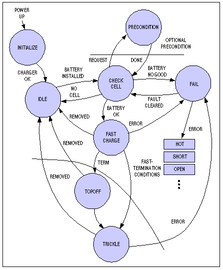
Figure 1. Generic charger-state diagram. InitializationThough not a part of the actual charging procedure, initialization is an important stage in the process. The charger initializes itself and performs its own self-test. A charge can be interrupted by a power failure and consequent reinitialization. Without a smart battery or some type of time-stamped, nonvolatile storage, such events can occur unnoticed. Most chargers reinitialize themselves fully after a power failure. If overcharging is an issue, the charger can then execute a special self-test sequence to determine if the battery is already charged. A battery present on power-up, for example, should trigger such an action.
Several circumstances can allow this initialization to cause charging problems. A fixed-time charger, for example, applies charge to a battery for a fixed interval of four hours. If a power failure occurs three hours and 59 minutes into the charge, the charger starts another four-hour charge, giving the battery a four-hour overcharge. This treatment can damage the battery, and it is one reason fixed-time charging is seldom used. The example also shows why the charger should monitor battery temperature or use other termination methods as a backup measure. Cell QualificationThis phase of the charging procedure detects when a battery is installed and whether it can be charged. Cell detection is usually accomplished by looking for voltage on the charger terminals while the charger source is off, but that method can pose a problem if the cells have been deeply cycled and are producing little voltage. As an alternative, the charger often looks for a thermistor or shorting jumper rather than the cell itself. The presence of this hardware can also serve to identify the battery pack. Smart batteries, on the other hand, conduct a rich exchange of serial data with the battery pack, usually providing all the necessary charging parameters over a specialized I²C-like protocol called the System Management Bus (SMBus™).
Once the charger determines that a cell is installed, it must determine if the cell is good. During this subphase (qualification), the cell is checked for basic functioning: open, shorted, hot, or cold. To test whether or not a cell is chargeable, some chargers-lead-acid types especially-apply a light charging current (about one-fifth of the fast rate) and allow the cell a fixed amount of time to reach a specified voltage. This technique avoids the problem of false rejects for deeply cycled PbSO4 batteries, and with the battery manufacturer's approval, it can be used for other chemistries as well.
A check of the ambient and cell temperatures is also a part of the qualification phase. When a charger detects high or low temperature, it usually waits a predetermined interval for the temperature to return to nominal. If this doesn't happen within the allotted time, the charger reduces the charging current. This action in turn reduces battery temperature, which increases efficiency. Finally, the cells are checked for opens and shorts. Open cells are easily detected, but a shorted-cell indication requires confirmation in order to avoid false failure indications. If all of these checks are satisfactory, the cell can be charged, and the state is advanced as shown in Figure 1. Preconditioning Phase (optional)Some chargers (primarily those for NiCd batteries) include an optional preconditioning phase in which the battery is fully discharged before recharging. Full discharge reduces each battery's voltage level to 1V per cell and eliminates dendritic formations in the electrolyte, which cause what is often falsely labeled the memory effect. This so-called memory effect refers to the presence of dendritic formations that can reduce the run life of a cell, but a complete charge and discharge cycle sometimes eliminates the problem.
Preconditioning can be accomplished before each charge, or it can follow an indication (by load test or other operation) that more than half of the cell's charge remains. Preconditioning can last from one to ten hours. Discharging a battery in less than one hour is not generally recommended. Fast preconditioning raises the practical problem of what to do with heat dissipated by the load resistor. Nor is preconditioning for longer than ten hours usually recommended unless it can be initiated manually upon detection of reduced capacity. Confusion and misunderstanding surround the NiCd "memory effect," so the designer should avoid putting a button on the charger to counteract it. Fast-Charge Phase and TerminationFast-charge and termination methods used depend on cell chemistry and other design factors. The following discussion covers fast-charging techniques widely used for today's common battery chemistries. For specific guidelines and recommendations, consult the battery manufacturer's applications department.
NiCd and NiMH CellsFast-charging procedures for NiCd and NiMH batteries are very similar; they differ primarily in the termination method used. In each case, the charger applies a constant current while monitoring battery voltage and other variables to determine when to terminate the charge. Fast-charge rates in excess of 2C are possible, but the most common rate is about C/2. Because charging efficiency is somewhat less than 100%, a full charge at the C/2 rate requires slightly more than two hours.
While constant current is applied, the cell voltage rises slowly and eventually reaches a peak (a point of zero slope). NiMH charging should be terminated at this peak (the 0DV point). NiCd charging, on the other hand, should terminate at a point past the peak: when the battery voltage first shows a slight decline (-DV) (Figure 2). Cell damage can result if fast charge continues past either battery's termination point.
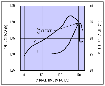
Figure 2. NiCd battery-charging characteristics at C/2 rate.
At rates exceeding C/2 (resulting in a charge time of no more than two hours), the charger also monitors the cell's temperature and voltage. Because cell temperature rises rapidly when a cell reaches full charge, the temperature monitor enables another termination technique. Termination on this positive temperature slope is called DT termination. Other factors that can trigger termination include charging time and maximum cell voltage. Well-designed chargers rely on a combination of these factors.
Note: Because certain effects that appear when a cell first begins charging can imitate termination conditions, chargers usually introduce a delay of one to five minutes before activating slope-detection termination modes. Also, charge-termination conditions are difficult to detect for rates below C/8, because the voltage and temperature slopes of interest (DV/Dt and DT/Dt) are small and comparable to other system effects. For safety during a fast charge, the hardware and software in these systems should always err on the side of earlytermination.
Lithium-Ion CellsLi+ battery charging differs from the nickel-chemistry charging schemes. A top-off charge can follow to ensure maximum energy storage in a safe manner. Li+ chargers regulate their charging voltage to an accuracy better than 0.75%, and their maximum charging rate is set with a current limit, much like that of a bench power supply (Figure 3). When fast charging begins, the cell voltage is low, and charging current assumes the current-limit value.
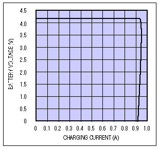
Figure 3. Li+ battery voltage vs. charging current.
Battery voltage rises slowly during the charge. Eventually, the current tapers down, and the voltage rises to a float-voltage level of 4.2V per cell (Figure 4).
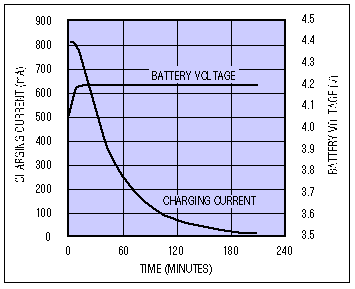
Figure 4. Li+ battery-charging profile.
The charger can terminate charging when the battery reaches its float voltage, but that approach neglects the topping-off operation. One variation is to start a timer when float voltage is reached, and then terminate charging after a fixed delay. Another method is to monitor the charging current, and terminate at a low level (typically 5% of the limit value; some manufacturers recommend a higher minimum of 100mA). A top-off cycle often follows this technique, as well.
The past few years have yielded improvements in Li+ batteries, the chargers, and our understanding of this battery chemistry. The earliest Li+ batteries for consumer applications had shortcomings that affected safety, but those problems cannot occur in today's well-designed systems. Manufacturers' recommendations are neither static nor totally consistent, and Li+ batteries continue to evolve.
Lead-Acid CellsPbSO4 batteries are usually charged either by the current-limited method or by the more common and generally simpler voltage-limited method. The voltage-limited charging method is similar to that used for Li+ cells, but high precision isn't as critical. It requires a current-limited voltage source set at a level somewhat higher than the cell's float voltage (about 2.45V).
After a preconditioning operation that ensures that the battery will take a charge, the charger begins the fast charge and continues until it reaches a minimum charging current. (This procedure is similar to that of a Li+ charger). Fast charge is then terminated, and the charger applies a maintenance charge of VFLOAT (usually about 2.2V). PbSO4 cells allow this float-voltage maintenance for indefinite periods (Figure 5).
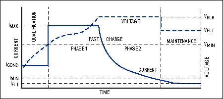
Figure 5. PbSO4 battery-charging profile.
At higher temperatures, the fast-charge current for PbSO4 batteries should be reduced according to the typical temperature coefficient of 0.3% per degree centigrade. The maximum temperature recommended for fast charging is about 50°C, but maintenance charging can generally proceed above that temperature. Optional Top-Off Charge (All chemistries)Chargers for all chemistries often include an optional top-off phase. This phase occurs after fast-charge termination and applies a moderate charging current that boosts the battery up to its full-charge level. (The operation is analogous to topping off a car's gas tank after the pump has stopped automatically.) The top-off charge is terminated on reaching a limit with respect to cell voltage, temperature, or time. In some cases, top-off charge can provide a run life of 5% or even 10% above that of a standard fast charge. Extra care is advisable here: the battery is at or near full charge and is therefore subject to damage from overcharging. Optional Trickle Charge (All chemistries except Li+)Chargers for all chemistries often include an optional trickle-charge phase. This phase compensates for self-discharge in a battery. PbSO4 batteries have the highest rate of self-discharge (a few percent per day), and Li+ cells have the lowest. The Li+ rate is so low that trickle charging is not required or recommended. NiCds, however, can usually accept a C/16 trickle charge indefinitely. For NiMH cells, a safe continuous current is usually around C/50, but trickle charging for NiMH cells is not universally recommended.
Pulsed trickle is a variation in which the charger provides brief pulses of approximately C/8 magnitude, with a low duty cycle that provides a typical average trickle current of C/512. Because pulsed-trickle charging applies to both nickel chemistries and lends itself well to the on/off type of microprocessor (µP) control, it is used almost universally. Generic Charging SystemBefore looking at specific circuit implementations, designers should become familiar with generic blocks and features (Figure 6). All fast chargers should include these block functions in some form. The bulk power source provides raw dc power, usually from a wall cube or brick. The current and voltage controls regulate current and voltage applied to the battery. For less-expensive chargers, the regulator is usually a power transistor or other linear-pass element that dissipates power as heat. It can also be a buck switching supply that includes a standard freewheeling diode for average efficiency or a synchronous rectifier for highest efficiency.
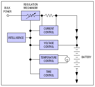
Figure 6. Generic charging-system block diagram.
The blocks on the right in Figure 6 represent various measurement and control functions. An analog current-control loop limits the maximum current delivered to the battery, and a voltage loop maintains a constant voltage on the cell. (Note that Li+ cells require a high level of precision in the applied charging voltage.)
A charger's current-voltage (I-V) characteristic can be fully programmable, or it can be programmable in current only, with a voltage limit (or vice versa). Cell temperature is always measured, and charge termination can be based either on the level or the slope of this measurement. Chargers also measure charging time, usually as a calculation in the intelligence block.
This block provides intelligence for the system and implements the state machine previously described. It knows how and when to terminate a fast charge. Intelligence is internal to the chip in stand-alone charger ICs. Otherwise, it resides in a host µC, and the other hardware blocks reside in the charger IC. As mentioned previously, this latter architecture is the one preferred today. Overview of Maxim's Charger OfferingsMaxim manufactures a broad selection of stand-alone and controller-type battery-charger ICs. The variety enables a system designer to make tradeoffs in performance, features, and cost. Table 1 lists these ICs by the battery chemistry supported, in their order of introduction, with the most recent models at the top.
Table 1. Overview of Maxim's Battery-Charger ICs
欢迎分享,转载请注明来源:内存溢出
赞
(0)
打赏
 微信扫一扫
微信扫一扫
 支付宝扫一扫
 微信扫一扫
微信扫一扫
 支付宝扫一扫
用于轻型车辆发电机的新型超低损耗二极管可减少二氧化碳排放
上一篇
2022-08-04
大功率晶闸管参数解析之正向特性
下一篇
2022-08-04

评论列表(0条)