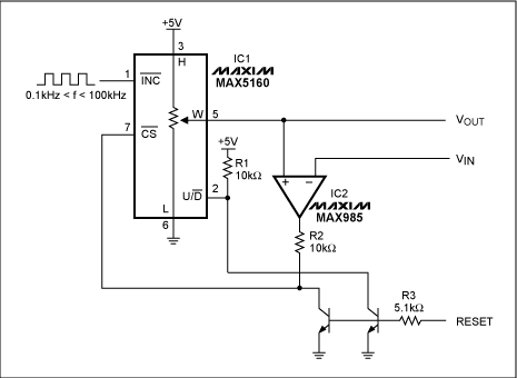
Most peak detectors employ a rectifier and a sample-and-hold circuit, which is prone to output droop. In an alternative approach, shown in the figure below, a 5-bit digital potentiometer with a servo loop is used to create an inexpensive peak detector with a logic-level reset input and no output droop.
Comparator control of IC1's chip-select input ensures that the digital potentiometer becomes active only when VIN exceeds the VOUT level currently latched, and R1 ensures that the potentiometer increments upward (rather than downward) as a result. When VI rises above VOUT, the comparator output (IC2) swings low and selects IC1, allowing the wiper position to increment upwards with each high-to-low transition of the clock (INC*). When VOUT reaches VIN, the comparator output goes high and latches VOUT at that level.
VOUT ranges between the voltage levels connected to the upper and lower extremes of the digital pot (5V and 0V in this case) in 32 equally spaced increments. By reducing this VOUT range, the size of an LSB can be decreased, thereby increasing the output resolution.
Most peak detectors employ a capacitor for holding the output voltage, and the droop (slow change) in VOUT caused by the capacitor's leakage current is particularly noticeable with low frequency or low duty cycle signals. The primary advantage of this circuit is the complete absence of such output droop. It holds the output level indefinitely, making it useful as a long-term memory.

Unlike peak detectors that use a capacitor to hold the output voltage, this design includes a digital potentiometer (IC1) that holds the output level indefinitely, without droop.
*This indicates the inverse of the signal.
A similar version of this article appeared in the May 15, 2000 issue of Electronic Design.
欢迎分享,转载请注明来源:内存溢出

 微信扫一扫
微信扫一扫
 支付宝扫一扫
评论列表(0条)