The MAX1455 has a unique feature: programmable analog clip-levels on the output signal. This feature can detect open circuits and short circuits in the wiring harness and connectors. It can also detect failed sensors.
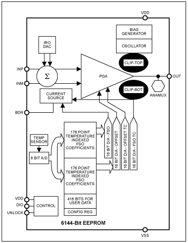
The output clip functions, Clip-Top and Clip-Bot, set the upper and lower output voltage limits of the programmable gain amplifier (PGA). The clip functions are highlighted in the MAX1455 block diagram in Figure 1.

Figure 1. Block diagram shows the diagnostic functions clip-top and clip-bot at the PGA output.
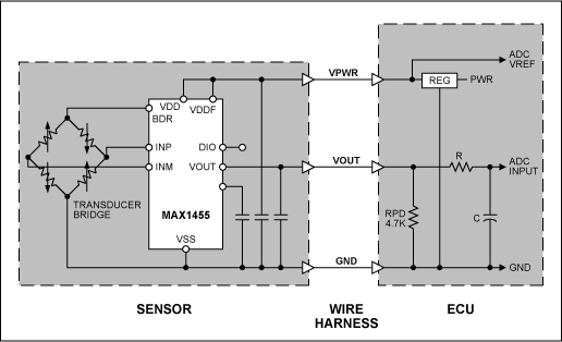
A typical application diagram is shown in Figure 2. The sensor assembly contains a pressure or force transducer and the MAX1455 signal conditioning IC. A wiring harness joins the sensor assembly to the primary Electronic Control Unit (ECU). The ECU provides the power-supply voltage (5V typical) to the sensor and receives the analog voltage signal from the sensor. The three harness wires are often bundled with other wires and may pass through several connector systems between the sensor and the ECU. It is desirable to detect an open circuit in the wires or connectors so that the ECU can take appropriate action. This action may consist of shutting down a subsystem, disregarding all measurements on the suspect line, or activating warning lights to indicate the fault condition.

Figure 2. Typical sensor wiring configuration.
It has become common practice to use a pull-up or pull-down resistor on the Vout line in the ECU that will pull the line to a defined state when the Vout line is an open circuit, as shown in Figure 2. Values for RPU or RPD of 2.2KΩ to 10KΩ have been used. When the Vout line is an open circuit the resistor pulls the line to a supply-rail and keeps it stable at that value. Normally this would be confused with a no-load, or full-scale load condition. By limiting the normal operating output of the sensor to values that are slightly away from the supply-rail voltages, a supply-rail voltage then is defined as an anomaly or fault condition (i.e., an open circuit in the Vout line).
When low values of RPU or RPD are used, and precise control of the clip voltage value is desired, it is sometimes necessary to buffer the clipped voltage to prevent the load from pulling the Vout signal away from the programmed clip setting.
The possible clip voltage settings for the MAX1455 are shown in Table 1.
Table 1. Output Clip Voltage Settings with VDD = 5.0VDC
欢迎分享,转载请注明来源:内存溢出
赞
(0)
打赏
 微信扫一扫
微信扫一扫
 支付宝扫一扫
 微信扫一扫
微信扫一扫
 支付宝扫一扫
网络视频监控谁是有领头人
上一篇
2022-08-05
移动监控与网络摄像机具备什么特点
下一篇
2022-08-05

评论列表(0条)