Error[8]: Undefined offset: 33, File: /www/wwwroot/outofmemory.cn/tmp/plugin_ss_superseo_model_superseo.php, Line: 114
File: /www/wwwroot/outofmemory.cn/tmp/plugin_ss_superseo_model_superseo.php, Line: 473, decode(

Abstract: This [+++]lica[+++]on no[+++] provides an example of hardware and software for interfacing an S[+++]™ real-TIme clock (RTC) to a Motorola® digital signal processor ([+++]) that has a built-in SPI-interface module. This example uses a Motorola DSP Demo Kit as the basis for the circuit.

Circuit DescripTIonThe DS3234 real-TIme clock (RTC) [+++] be interfaced to a [+++]crocontroller (µC) or digital signal processor (DSP) unit using an SPI-compatible interface. This application note shows how to connect a DS3234 to a Motorola DSP that has a built-in SPI module. This circuit uses the Motorola DSP56F800DEMO Demonstration Board and CodeWarrior™ integrated development environment (IDE). Figure 1 illustrates the pin configuration of the DS3234.
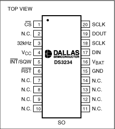
Figure 1. The pin configuration of the DS3234. Note that all N.C. pins must be connected to ground.

Using the Example SoftwareThe example software was developed by starting with a blank project. Follow the instructions in the Motorola Kit Installation Guide (Tutorial: Creating a CodeWarrior Project), and, then, [+++]d the code included in this application note in DS3234.c.

OperationThe prog[+++] uses a GPIO port to control the active-low CS pin on the DS3234. Another GPIO port is used to monitor the active-low INT/SQW pin. The software initializes the SPI and SCI controller modules in the DSP. The DS3234 supports SPI Modes 1 and 3. The SCI interface is used to provide program control on a terminal [+++] an [+++]-232 interface. The following six user-selected routines are provided: Write user-entered time and date values to the RTC, read the time and date, read SRAM, write SRAM, read the temperature, and read ten times using the active-low INT/SQW output in once-per-second al[+++] mode.

Figure 2 shows a schematic of the circuit. This circuit comprises a daughter card that is attached to the Motorola Demonstration Board. Please note that the circuit in Figure 2 includes several RTCs with SPI buses. Only one RTC may be used at a time, and the software only supports the DS3234.
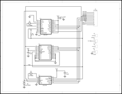
Figure 2. This schematic illustrates the connections for interfacing the DS3234 and other RTCs with SPI buses to a Motorola DSP.
More detai[+++] image (PDF, 138kB)
Figure 2. This schematic illustrates the connections for interfacing the DS3234 and other RTCs with SPI buses to a Motorola DSP.

The example software code for interfacing a DS3234 SPI-bus RTC to a Motorola DSP is as follows:

/* File: DS3234.c */
/* This example program was developed using the Motorola
56F800 Demo Board Kit.  Follow the kit instalation guide
for creating a CodeWarrior Project.  Use the shell of the
new project for this example.  Note: This program is for
example only and is not supported by Maxim. */

#include "port.h"
#include "stdio.h"
#include "stdlib.h"
#include "appconfig.h"
#include "string.h"

/*******************************************************
* M[+++]n program for use with Embedded SDK
*******************************************************/

void reset_spi(void);
void wbyte_spi(unsigned char);
void init_sci0(Word16);
void tx_sci0(unsigned char);
unsigned char rx_sci0();
UWord16 input_data(void);
void output_data(unsigned char *);
void bcd2ascii(unsigned char);
void int2ascii(unsigned char);
unsigned char  rbyte_spi(void);
void init_3234(void);
void rd_rtc(void);
void rd_ram(void);
void wr_ram(void);
void rd_temp(void);
void init_alarm(void);
void loop_rd(void);

unsigned char   min, sec, hr, dow, date, mon, yr;

#define REG_BASE 0x0000
#define SCI0_BASE 0x0F00
#define SPI_BASE 0x0F20
#define GPIOA_BASE 0x0FB0
#define GPIOB_BASE 0x0FC0

#define SCI0_SCIBR *(volatile UWord16 *)(SCI0_BASE + 0)
#define SCI0_SCICR *(volatile UWord16 *)(SCI0_BASE + 1)
#define SCI0_SCISR *(volatile UWord16 *)(SCI0_BASE + 2)
#define SCI0_SCIDR *(volatile UWord16 *)(SCI0_BASE + 3)

#define SPSCR *(volatile UWord16 *)(SPI_BASE + 0)
#define SPDSR *(volatile UWord16 *)(SPI_BASE + 1)
#define SPDRR *(volatile UWord16 *)(SPI_BASE + 2)
#define SPDTR *(volatile UWord16 *)(SPI_BASE + 3)

#define GPIO_A_PUR *(volatile UWord16 *)(GPIOA_BASE + 0)
#define GPIO_A_DR *(volatile UWord16 *)(GPIOA_BASE + 1)
#define GPIO_A_DDR *(volatile UWord16 *)(GPIOA_BASE + 2)
#define GPIO_A_PER *(volatile UWord16 *)(GPIOA_BASE + 3)

#define GPIO_B_PUR *(volatile UWord16 *)(GPIOB_BASE + 0)
#define GPIO_B_DR *(volatile UWord16 *)(GPIOB_BASE + 1)
#define GPIO_B_DDR *(volatile UWord16 *)(GPIOB_BASE + 2)
#define GPIO_B_PER *(volatile UWord16 *)(GPIOB_BASE + 3)

void main (void)
{
unsigned char val;

        reset_spi();
        init_sci0(195);                 // 30MHz / 195 = 9600 baud

        GPIO_B_DR = 0x0008;             // disable RTC - CS high

        GPIO_B_DR = 0;                  // enable RTC - CS low
        wbyte_spi(0x8e);                // control register write address
        rbyte_spi();                    // dummy read
        wbyte_spi(0x18);                // enable osc, 8kHz on INTb/SQW
        rbyte_spi();

        GPIO_B_DR = 0x0008;             // disable RTC - CS high

        while(1)
        {
                output_data("\n\rDS3234 build: \0");
                output_data(__DATE__);
                output_data("\n\rR)ead RTC   W)rite RTC\0");
                output_data("\n\rT)emp rd    L)oop rd w/INTb\0");
                output_data("\n\rE)xt RAM rd wrI)te RAM\0");
                output_data("\n\rEnter command: \0");
                val = rx_sci0();

                switch(val)
                {
                        case 'E':
                        case 'e':       rd_ram();       break;

                        case 'I':
                        case 'i':       wr_ram();       break;

                        case 'L':
                        case 'l':       loop_rd();      break;

                        case 'R':
                        case 'r':       rd_rtc();       break;

                        case 'T':
                        case 't':       rd_temp();      break;

                        case 'W':
                        case 'w':       init_3234();    break;
                }
        }

        return;
}

//SPSCR
//15 14  13   12     11   10    9     8    7       6       5    4        3    2    1    0
// r MSB SPRF ERRIE  o[+++]f modf spte modfen spr1   spr0   sprie spmstr   cpol cpha spe  spite

void reset_spi()
{
int     val;
        SPSCR = 0x0056; // SPR0, SPMSTR, CPHA, SPE
        SPDSR = 0x0007; // 8-bit size

        SPSCR &= 0xfffd;        // clear spe, resets SPI (partial)
        SPSCR |= 0x0002;        // set spe, new values take effect

        GPIO_B_PER = 0x00f3;    // use GPIOB3 as CS for RTC, GPIOB2 as input
        GPIO_B_DDR = 0x0009;    // direction is output for CS

        GPIO_A_PER = 0x00f9;    // enable/disable per function (1=enable)
        GPIO_A_DDR = 0x0006;    // direction is output (1=output)
        GPIO_A_DR  = 0;                 // write bits low (0=low)
}

void  wbyte_spi( unsigned char  wbyte)  // ------ write one byte -------
{
        while (!(SPSCR & 0x0200));      // wait for transmitter empty flag

        SPDTR = wbyte;  
}

void    bcd2ascii(unsigned char dat)    // ----- convert bcd to ascii and send to sci ----
{
        [+++]( (dat >> 4) > 9)
                tx_sci0( (dat >> 4) + 0x37);    // A - F
        else
                tx_sci0( (dat >> 4) + 0x30);    // 0 - 9

        if( (dat & 0x0f) > 9)
                tx_sci0( (dat & 0x0f) + 0x37);
        else
                tx_sci0( (dat & 0x0f) + 0x30);
}
void    int2ascii(unsigned char dat)    // ----- convert int to ascii and send to sci ----
{
unsigned char tmp1;

        if(dat > 99)
        {
                tmp1 = (dat / 100) + 0x30;      // if > 100, convert to ASCII 1
                tx_sci0(tmp1);
                dat -= (100 * (int) (dat / 100) );      // adjust number
        }
        if(dat > 9)
        {
                tmp1 = (dat / 10) + 0x30;       // if > 10, convert to ASCII 1
                tx_sci0(tmp1);
                dat -= (10 * (int) (dat / 10) );        // adjust number
        }

                tmp1 = (dat) + 0x30;    // convert to ASCII 1
                tx_sci0(tmp1);
}
unsigned char rbyte_spi(void)   // -------- read one byte ----------
{
        while (!(SPSCR & 0x2000));      // wait for receiver full flag

        return(SPDRR);
   
}
void    init_sci0(Word16 baud)  // ---- initialize SCI0 for RS232 comm ---
{
        GPIO_B_PER = 0x00f3;    // set up
        GPIO_B_DDR = 0x0009;    // direction is output

        SCI0_SCIBR = baud;              // baud rate
        SCI0_SCICR = 0x2000;    // control reg
}
void tx_sci0(unsigned char val) // ------ transmit one char from SCI -----
{
UWord16 dat;

        SCI0_SCICR &= 0x3ffb;   // turn receiver off
        SCI0_SCICR |= 8;                // turn transmitter on
        while(!(SCI0_SCISR & 0x8000));  // wait until TDRE is false
        while(!(SCI0_SCISR & 0x4000));  // wait until TIDLE is false

        SCI0_SCIDR = (Word16) (val);


        while(!(SCI0_SCISR & 0x8000));  // wait until TDRE is false
        while(!(SCI0_SCISR & 0x4000));  // wait until TIDLE is false

        SCI0_SCICR &= 0x3ff0;   // turn transmitter off
}
unsigned char rx_sci0() // ------ receive one char to SCI -----
{
        SCI0_SCICR &= 0x3ff0;   // turn transmitter off
        SCI0_SCICR |= 4;                // turn receiver on

        while(!(SCI0_SCISR & 0x2000));  // wait until RDRF is true

        SCI0_SCICR &= 0x3ffb;   // turn receiver off

        return( (unsigned char) (SCI0_SCIDR & 0x00FF) );
}
UWord16 input_data()    // -------- get string --------------
{
UWord16 dat = 0, tmp[2] = {0,0};
        while(1)
        {
                dat = (rx_sci0() & 0x00ff);     // get a character
                if(dat == 0x0d)
                {
                        tmp[0] = (tmp[0] & 0x000f);     // convert ASCII 0-9
                        tmp[1] = (tmp[1] & 0x000f);     //  to 'BCD'
                        dat = (tmp[1] << 4) + tmp[0];
                        return(dat);    // exit if lf
                }
                tx_sci0(dat);   // echo new char to screen
                tmp[1] = tmp[0];        // move it
                tmp[0] = dat;
        }
        return(dat);    // return BCD (for ASCII 0-9 only)
}
void output_data(unsigned char str[80]) // -------- send string --------------
{
UWord16 dat, inc = 0;

        do
        {
                dat = str[inc];
                tx_sci0(dat);   // new char to screen
                inc++;
        }       while(str[inc]);        // quit when char is NULL
}
void init_3234(void)    // ----- init RTC using user values -----
{
        output_data("Enter year 00-99 < 10; inc++)   // loop 10 times then exit
        {
                while(GPIO_B_DR & 0x0004);      // loop while GPIO is high
                rd_rtc();       // output time & date
        
                GPIO_B_DR = 0u;         // enable RTC - CS low

                wbyte_spi(0x0f);        // control/status register
                rbyte_spi();            // dummy read
                wbyte_spi(0);
                val = rbyte_spi();      // read current data in register

                GPIO_B_DR = 0x0008;     // disable RTC - CS high
        
                GPIO_B_DR = 0u;         // enable RTC - CS low

                wbyte_spi(0x8f);        // control/status register
                rbyte_spi();            // dummy read
                wbyte_spi(val & 0xfc);  // clear AF flags, leave other bits unchanged
                rbyte_spi();            // dummy read

                GPIO_B_DR = 0x0008;     // disable RTC - CS high
        }
}
"); yr = (unsigned char) input_data(); output_data("\n\rEnter month 1-12

"); mon = (unsigned char) input_data(); output_data("\n\rEnter date 1-31
"); date = (unsigned char) input_data(); output_data("\n\rEnter day of week 1-7
"); dow = (unsigned char) input_data(); output_data("\n\rEnter hour 1-23
"); hr = (unsigned char) input_data(); output_data("\n\rEnter minute 0-59 "); min = (unsigned char) input_data(); output_data("\n\rEnter second 0-59

"); sec = (unsigned char) input_data(); GPIO_B_DR = 0u; // enable RTC - CS low wbyte_spi(0x80); // select seconds register write address rbyte_spi(); // dummy read wbyte_spi(sec); // seconds register data rbyte_spi(); wbyte_spi(min); // minutes register rbyte_spi(); wbyte_spi(hr); // hours register rbyte_spi(); wbyte_spi(dow); // day of week register rbyte_spi(); wbyte_spi(date); // date register rbyte_spi(); wbyte_spi(mon); // month register rbyte_spi(); wbyte_spi(yr); // year register rbyte_spi(); GPIO_B_DR = 0x0008; // disable RTC - CS high } void rd_rtc(void) // ---- loop reading time & date ---- { GPIO_B_DR = 0u; // enable RTC - CS low wbyte_spi(0); // seconds register read address rbyte_spi(); // dummy read wbyte_spi(0); sec = rbyte_spi(); // read seconds register wbyte_spi(0); min = rbyte_spi(); // ditto minutes wbyte_spi(0); hr = rbyte_spi(); // and so on wbyte_spi(0); dow = rbyte_spi(); wbyte_spi(0); date = rbyte_spi(); wbyte_spi(0); mon = rbyte_spi(); wbyte_spi(0); yr = rbyte_spi(); GPIO_B_DR = 0x0008; // disable RTC - CS high tx_sci0(0x0d); // sequence to print crlf tx_sci0(0x0a); bcd2ascii(yr); // sequence to print time & date tx_sci0('/'); bcd2ascii(mon); tx_sci0('/'); bcd2ascii(date); tx_sci0(' '); bcd2ascii(hr); tx_sci0(':'); bcd2ascii(min); tx_sci0(':'); bcd2ascii(sec); } void rd_ram(void) // ---- read & display RAM data ---- { UWord16 inc; unsigned char dat; GPIO_B_DR = 0u; // enable RTC - CS low wbyte_spi(0x98); // SRAM address register, write rbyte_spi(); // dummy read wbyte_spi(0); // set the SRAM address rbyte_spi(); // dummy read GPIO_B_DR = 0x0008; // disable RTC - CS high GPIO_B_DR = 0u; // enable RTC - CS low // register pointer auto-incremented to the SRAM data register, // where it will stay wbyte_spi(0x19); // SRAM data register, read rbyte_spi(); // dummy read tx_sci0(0x0d); // sequence to print crlf tx_sci0(0x0a); for(inc = 0; inc < 256; inc++) { wbyte_spi(0); // dummy write dat = rbyte_spi(); // read the data if(!(inc % 16) ) { tx_sci0(0x0d); // sequence to print crlf tx_sci0(0x0a); } bcd2ascii(dat); tx_sci0(' '); // print a space // the SRAM address in the SRAM address register increments // each time the SRAM data register is read or written } GPIO_B_DR = 0x0008; // disable RTC - CS high } void wr_ram(void) // ---- write incrementing data to RAM ---- { UWord16 inc; GPIO_B_DR = 0u; // enable RTC - CS low wbyte_spi(0x98); // SRAM address register, write rbyte_spi(); // dummy read wbyte_spi(0); // set the SRAM address rbyte_spi(); // dummy read // register pointer auto-incremented to the next location // and stays there (if it's the RAM data register) for(inc = 0; inc < 256; inc++) { wbyte_spi( (unsigned char) inc); rbyte_spi(); // dummy read } GPIO_B_DR = 0x0008; // disable RTC - CS high // We could set the SRAM address each time we write a byte // of data, which would be the case if you need to randomly // access data in the SRAM } void rd_temp(void) // ------ read temperature register ------ { unsigned char msb, lsb; do { GPIO_B_DR = 0u; // enable RTC - CS low wbyte_spi(0x0f); // control/status reg rbyte_spi(); // dummy read wbyte_spi(0); // dummy write msb = rbyte_spi(); // read reg GPIO_B_DR = 0x0008; // disable RTC - CS high } while(msb & 0x04); // wait if BSY = 1 GPIO_B_DR = 0u; // enable RTC - CS low wbyte_spi(0x11); // address of temperature MSB rbyte_spi(); // dummy read wbyte_spi(0); msb = rbyte_spi(); // read MSB wbyte_spi(0); lsb = (rbyte_spi() >> 6) * 25; // read LSB GPIO_B_DR = 0x0008; // disable RTC - CS high int2ascii(msb); tx_sci0('.'); int2ascii(lsb); } void init_alarm(void) // --- enable alarm 1 for once-per-second --- { GPIO_B_DR = 0u; // enable RTC - CS low wbyte_spi(0x87); // 1st alarm 1 reg address rbyte_spi(); // dummy read wbyte_spi(0x80); // mask alarm register rbyte_spi(); // dummy read wbyte_spi(0x80); rbyte_spi(); // dummy read wbyte_spi(0x80); rbyte_spi(); // dummy read wbyte_spi(0x80); rbyte_spi(); // dummy read GPIO_B_DR = 0x0008; // disable RTC - CS high GPIO_B_DR = 0u; // enable RTC - CS low wbyte_spi(0x8e); // control register rbyte_spi(); // dummy read wbyte_spi(0x05); // enable interrupts, alarm 1 output rbyte_spi(); // dummy read /* Good practice would dictate that we clear any alarm flags that may already have been set or else we run the risk that the handling routine may be invoked immediately. For this example, it's not necessary */ GPIO_B_DR = 0x0008; // disable RTC - CS high } void loop_rd(void) // --- output time & date when INTb/SQW goes active --- { /* This routine shows how to handle an alarm from the RTC. In actual use, an interrupt routine would normally be used to service an interrupt from the RTC. An alarm could be used to wake up a micro so that it could pe[+++]orm some function, set a new alarm time, and go back to sleep */ unsigned char val, inc; init_alarm(); // enable alarm 1 for(inc = 0; inc <===> <===>CodeWarrior is a trademark of Freescale Semiconductor, Inc.<===>Motorola is a registered trademark of Motorola, Inc.<===>SPI is a trademark of Motorola, Inc.<===><===><===>)
File: /www/wwwroot/outofmemory.cn/tmp/route_read.php, Line: 126, InsideLink()
File: /www/wwwroot/outofmemory.cn/tmp/index.inc.php, Line: 165, include(/www/wwwroot/outofmemory.cn/tmp/route_read.php)
File: /www/wwwroot/outofmemory.cn/index.php, Line: 30, include(/www/wwwroot/outofmemory.cn/tmp/index.inc.php)
Error[8]: Undefined offset: 34, File: /www/wwwroot/outofmemory.cn/tmp/plugin_ss_superseo_model_superseo.php, Line: 114
File: /www/wwwroot/outofmemory.cn/tmp/plugin_ss_superseo_model_superseo.php, Line: 473, decode(

Abstract: This [+++]lica[+++]on no[+++] provides an example of hardware and software for interfacing an S[+++]™ real-TIme clock (RTC) to a Motorola® digital signal processor ([+++]) that has a built-in SPI-interface module. This example uses a Motorola DSP Demo Kit as the basis for the circuit.

Circuit DescripTIonThe DS3234 real-TIme clock (RTC) [+++] be interfaced to a [+++]crocontroller (µC) or digital signal processor (DSP) unit using an SPI-compatible interface. This application note shows how to connect a DS3234 to a Motorola DSP that has a built-in SPI module. This circuit uses the Motorola DSP56F800DEMO Demonstration Board and CodeWarrior™ integrated development environment (IDE). Figure 1 illustrates the pin configuration of the DS3234.

Figure 1. The pin configuration of the DS3234. Note that all N.C. pins must be connected to ground.

Using the Example SoftwareThe example software was developed by starting with a blank project. Follow the instructions in the Motorola Kit Installation Guide (Tutorial: Creating a CodeWarrior Project), and, then, [+++]d the code included in this application note in DS3234.c.

OperationThe prog[+++] uses a GPIO port to control the active-low CS pin on the DS3234. Another GPIO port is used to monitor the active-low INT/SQW pin. The software initializes the SPI and SCI controller modules in the DSP. The DS3234 supports SPI Modes 1 and 3. The SCI interface is used to provide program control on a terminal [+++] an [+++]-232 interface. The following six user-selected routines are provided: Write user-entered time and date values to the RTC, read the time and date, read SRAM, write SRAM, read the temperature, and read ten times using the active-low INT/SQW output in once-per-second al[+++] mode.

Figure 2 shows a schematic of the circuit. This circuit comprises a daughter card that is attached to the Motorola Demonstration Board. Please note that the circuit in Figure 2 includes several RTCs with SPI buses. Only one RTC may be used at a time, and the software only supports the DS3234.

Figure 2. This schematic illustrates the connections for interfacing the DS3234 and other RTCs with SPI buses to a Motorola DSP.
More detai[+++] image (PDF, 138kB)
Figure 2. This schematic illustrates the connections for interfacing the DS3234 and other RTCs with SPI buses to a Motorola DSP.

The example software code for interfacing a DS3234 SPI-bus RTC to a Motorola DSP is as follows:

/* File: DS3234.c */
/* This example program was developed using the Motorola
56F800 Demo Board Kit.  Follow the kit instalation guide
for creating a CodeWarrior Project.  Use the shell of the
new project for this example.  Note: This program is for
example only and is not supported by Maxim. */

#include "port.h"
#include "stdio.h"
#include "stdlib.h"
#include "appconfig.h"
#include "string.h"

/*******************************************************
* M[+++]n program for use with Embedded SDK
*******************************************************/

void reset_spi(void);
void wbyte_spi(unsigned char);
void init_sci0(Word16);
void tx_sci0(unsigned char);
unsigned char rx_sci0();
UWord16 input_data(void);
void output_data(unsigned char *);
void bcd2ascii(unsigned char);
void int2ascii(unsigned char);
unsigned char  rbyte_spi(void);
void init_3234(void);
void rd_rtc(void);
void rd_ram(void);
void wr_ram(void);
void rd_temp(void);
void init_alarm(void);
void loop_rd(void);

unsigned char   min, sec, hr, dow, date, mon, yr;

#define REG_BASE 0x0000
#define SCI0_BASE 0x0F00
#define SPI_BASE 0x0F20
#define GPIOA_BASE 0x0FB0
#define GPIOB_BASE 0x0FC0

#define SCI0_SCIBR *(volatile UWord16 *)(SCI0_BASE + 0)
#define SCI0_SCICR *(volatile UWord16 *)(SCI0_BASE + 1)
#define SCI0_SCISR *(volatile UWord16 *)(SCI0_BASE + 2)
#define SCI0_SCIDR *(volatile UWord16 *)(SCI0_BASE + 3)

#define SPSCR *(volatile UWord16 *)(SPI_BASE + 0)
#define SPDSR *(volatile UWord16 *)(SPI_BASE + 1)
#define SPDRR *(volatile UWord16 *)(SPI_BASE + 2)
#define SPDTR *(volatile UWord16 *)(SPI_BASE + 3)

#define GPIO_A_PUR *(volatile UWord16 *)(GPIOA_BASE + 0)
#define GPIO_A_DR *(volatile UWord16 *)(GPIOA_BASE + 1)
#define GPIO_A_DDR *(volatile UWord16 *)(GPIOA_BASE + 2)
#define GPIO_A_PER *(volatile UWord16 *)(GPIOA_BASE + 3)

#define GPIO_B_PUR *(volatile UWord16 *)(GPIOB_BASE + 0)
#define GPIO_B_DR *(volatile UWord16 *)(GPIOB_BASE + 1)
#define GPIO_B_DDR *(volatile UWord16 *)(GPIOB_BASE + 2)
#define GPIO_B_PER *(volatile UWord16 *)(GPIOB_BASE + 3)

void main (void)
{
unsigned char val;

        reset_spi();
        init_sci0(195);                 // 30MHz / 195 = 9600 baud

        GPIO_B_DR = 0x0008;             // disable RTC - CS high

        GPIO_B_DR = 0;                  // enable RTC - CS low
        wbyte_spi(0x8e);                // control register write address
        rbyte_spi();                    // dummy read
        wbyte_spi(0x18);                // enable osc, 8kHz on INTb/SQW
        rbyte_spi();

        GPIO_B_DR = 0x0008;             // disable RTC - CS high

        while(1)
        {
                output_data("\n\rDS3234 build: \0");
                output_data(__DATE__);
                output_data("\n\rR)ead RTC   W)rite RTC\0");
                output_data("\n\rT)emp rd    L)oop rd w/INTb\0");
                output_data("\n\rE)xt RAM rd wrI)te RAM\0");
                output_data("\n\rEnter command: \0");
                val = rx_sci0();

                switch(val)
                {
                        case 'E':
                        case 'e':       rd_ram();       break;

                        case 'I':
                        case 'i':       wr_ram();       break;

                        case 'L':
                        case 'l':       loop_rd();      break;

                        case 'R':
                        case 'r':       rd_rtc();       break;

                        case 'T':
                        case 't':       rd_temp();      break;

                        case 'W':
                        case 'w':       init_3234();    break;
                }
        }

        return;
}

//SPSCR
//15 14  13   12     11   10    9     8    7       6       5    4        3    2    1    0
// r MSB SPRF ERRIE  o[+++]f modf spte modfen spr1   spr0   sprie spmstr   cpol cpha spe  spite

void reset_spi()
{
int     val;
        SPSCR = 0x0056; // SPR0, SPMSTR, CPHA, SPE
        SPDSR = 0x0007; // 8-bit size

        SPSCR &= 0xfffd;        // clear spe, resets SPI (partial)
        SPSCR |= 0x0002;        // set spe, new values take effect

        GPIO_B_PER = 0x00f3;    // use GPIOB3 as CS for RTC, GPIOB2 as input
        GPIO_B_DDR = 0x0009;    // direction is output for CS

        GPIO_A_PER = 0x00f9;    // enable/disable per function (1=enable)
        GPIO_A_DDR = 0x0006;    // direction is output (1=output)
        GPIO_A_DR  = 0;                 // write bits low (0=low)
}

void  wbyte_spi( unsigned char  wbyte)  // ------ write one byte -------
{
        while (!(SPSCR & 0x0200));      // wait for transmitter empty flag

        SPDTR = wbyte;  
}

void    bcd2ascii(unsigned char dat)    // ----- convert bcd to ascii and send to sci ----
{
        [+++]( (dat >> 4) > 9)
                tx_sci0( (dat >> 4) + 0x37);    // A - F
        else
                tx_sci0( (dat >> 4) + 0x30);    // 0 - 9

        if( (dat & 0x0f) > 9)
                tx_sci0( (dat & 0x0f) + 0x37);
        else
                tx_sci0( (dat & 0x0f) + 0x30);
}
void    int2ascii(unsigned char dat)    // ----- convert int to ascii and send to sci ----
{
unsigned char tmp1;

        if(dat > 99)
        {
                tmp1 = (dat / 100) + 0x30;      // if > 100, convert to ASCII 1
                tx_sci0(tmp1);
                dat -= (100 * (int) (dat / 100) );      // adjust number
        }
        if(dat > 9)
        {
                tmp1 = (dat / 10) + 0x30;       // if > 10, convert to ASCII 1
                tx_sci0(tmp1);
                dat -= (10 * (int) (dat / 10) );        // adjust number
        }

                tmp1 = (dat) + 0x30;    // convert to ASCII 1
                tx_sci0(tmp1);
}
unsigned char rbyte_spi(void)   // -------- read one byte ----------
{
        while (!(SPSCR & 0x2000));      // wait for receiver full flag

        return(SPDRR);
   
}
void    init_sci0(Word16 baud)  // ---- initialize SCI0 for RS232 comm ---
{
        GPIO_B_PER = 0x00f3;    // set up
        GPIO_B_DDR = 0x0009;    // direction is output

        SCI0_SCIBR = baud;              // baud rate
        SCI0_SCICR = 0x2000;    // control reg
}
void tx_sci0(unsigned char val) // ------ transmit one char from SCI -----
{
UWord16 dat;

        SCI0_SCICR &= 0x3ffb;   // turn receiver off
        SCI0_SCICR |= 8;                // turn transmitter on
        while(!(SCI0_SCISR & 0x8000));  // wait until TDRE is false
        while(!(SCI0_SCISR & 0x4000));  // wait until TIDLE is false

        SCI0_SCIDR = (Word16) (val);


        while(!(SCI0_SCISR & 0x8000));  // wait until TDRE is false
        while(!(SCI0_SCISR & 0x4000));  // wait until TIDLE is false

        SCI0_SCICR &= 0x3ff0;   // turn transmitter off
}
unsigned char rx_sci0() // ------ receive one char to SCI -----
{
        SCI0_SCICR &= 0x3ff0;   // turn transmitter off
        SCI0_SCICR |= 4;                // turn receiver on

        while(!(SCI0_SCISR & 0x2000));  // wait until RDRF is true

        SCI0_SCICR &= 0x3ffb;   // turn receiver off

        return( (unsigned char) (SCI0_SCIDR & 0x00FF) );
}
UWord16 input_data()    // -------- get string --------------
{
UWord16 dat = 0, tmp[2] = {0,0};
        while(1)
        {
                dat = (rx_sci0() & 0x00ff);     // get a character
                if(dat == 0x0d)
                {
                        tmp[0] = (tmp[0] & 0x000f);     // convert ASCII 0-9
                        tmp[1] = (tmp[1] & 0x000f);     //  to 'BCD'
                        dat = (tmp[1] << 4) + tmp[0];
                        return(dat);    // exit if lf
                }
                tx_sci0(dat);   // echo new char to screen
                tmp[1] = tmp[0];        // move it
                tmp[0] = dat;
        }
        return(dat);    // return BCD (for ASCII 0-9 only)
}
void output_data(unsigned char str[80]) // -------- send string --------------
{
UWord16 dat, inc = 0;

        do
        {
                dat = str[inc];
                tx_sci0(dat);   // new char to screen
                inc++;
        }       while(str[inc]);        // quit when char is NULL
}
void init_3234(void)    // ----- init RTC using user values -----
{
        output_data("Enter year 00-99 < 10; inc++)   // loop 10 times then exit
        {
                while(GPIO_B_DR & 0x0004);      // loop while GPIO is high
                rd_rtc();       // output time & date
        
                GPIO_B_DR = 0u;         // enable RTC - CS low

                wbyte_spi(0x0f);        // control/status register
                rbyte_spi();            // dummy read
                wbyte_spi(0);
                val = rbyte_spi();      // read current data in register

                GPIO_B_DR = 0x0008;     // disable RTC - CS high
        
                GPIO_B_DR = 0u;         // enable RTC - CS low

                wbyte_spi(0x8f);        // control/status register
                rbyte_spi();            // dummy read
                wbyte_spi(val & 0xfc);  // clear AF flags, leave other bits unchanged
                rbyte_spi();            // dummy read

                GPIO_B_DR = 0x0008;     // disable RTC - CS high
        }
}
"); yr = (unsigned char) input_data(); output_data("\n\rEnter month 1-12

"); mon = (unsigned char) input_data(); output_data("\n\rEnter date 1-31
"); date = (unsigned char) input_data(); output_data("\n\rEnter day of week 1-7
"); dow = (unsigned char) input_data(); output_data("\n\rEnter hour 1-23
"); hr = (unsigned char) input_data(); output_data("\n\rEnter minute 0-59 "); min = (unsigned char) input_data(); output_data("\n\rEnter second 0-59

"); sec = (unsigned char) input_data(); GPIO_B_DR = 0u; // enable RTC - CS low wbyte_spi(0x80); // select seconds register write address rbyte_spi(); // dummy read wbyte_spi(sec); // seconds register data rbyte_spi(); wbyte_spi(min); // minutes register rbyte_spi(); wbyte_spi(hr); // hours register rbyte_spi(); wbyte_spi(dow); // day of week register rbyte_spi(); wbyte_spi(date); // date register rbyte_spi(); wbyte_spi(mon); // month register rbyte_spi(); wbyte_spi(yr); // year register rbyte_spi(); GPIO_B_DR = 0x0008; // disable RTC - CS high } void rd_rtc(void) // ---- loop reading time & date ---- { GPIO_B_DR = 0u; // enable RTC - CS low wbyte_spi(0); // seconds register read address rbyte_spi(); // dummy read wbyte_spi(0); sec = rbyte_spi(); // read seconds register wbyte_spi(0); min = rbyte_spi(); // ditto minutes wbyte_spi(0); hr = rbyte_spi(); // and so on wbyte_spi(0); dow = rbyte_spi(); wbyte_spi(0); date = rbyte_spi(); wbyte_spi(0); mon = rbyte_spi(); wbyte_spi(0); yr = rbyte_spi(); GPIO_B_DR = 0x0008; // disable RTC - CS high tx_sci0(0x0d); // sequence to print crlf tx_sci0(0x0a); bcd2ascii(yr); // sequence to print time & date tx_sci0('/'); bcd2ascii(mon); tx_sci0('/'); bcd2ascii(date); tx_sci0(' '); bcd2ascii(hr); tx_sci0(':'); bcd2ascii(min); tx_sci0(':'); bcd2ascii(sec); } void rd_ram(void) // ---- read & display RAM data ---- { UWord16 inc; unsigned char dat; GPIO_B_DR = 0u; // enable RTC - CS low wbyte_spi(0x98); // SRAM address register, write rbyte_spi(); // dummy read wbyte_spi(0); // set the SRAM address rbyte_spi(); // dummy read GPIO_B_DR = 0x0008; // disable RTC - CS high GPIO_B_DR = 0u; // enable RTC - CS low // register pointer auto-incremented to the SRAM data register, // where it will stay wbyte_spi(0x19); // SRAM data register, read rbyte_spi(); // dummy read tx_sci0(0x0d); // sequence to print crlf tx_sci0(0x0a); for(inc = 0; inc < 256; inc++) { wbyte_spi(0); // dummy write dat = rbyte_spi(); // read the data if(!(inc % 16) ) { tx_sci0(0x0d); // sequence to print crlf tx_sci0(0x0a); } bcd2ascii(dat); tx_sci0(' '); // print a space // the SRAM address in the SRAM address register increments // each time the SRAM data register is read or written } GPIO_B_DR = 0x0008; // disable RTC - CS high } void wr_ram(void) // ---- write incrementing data to RAM ---- { UWord16 inc; GPIO_B_DR = 0u; // enable RTC - CS low wbyte_spi(0x98); // SRAM address register, write rbyte_spi(); // dummy read wbyte_spi(0); // set the SRAM address rbyte_spi(); // dummy read // register pointer auto-incremented to the next location // and stays there (if it's the RAM data register) for(inc = 0; inc < 256; inc++) { wbyte_spi( (unsigned char) inc); rbyte_spi(); // dummy read } GPIO_B_DR = 0x0008; // disable RTC - CS high // We could set the SRAM address each time we write a byte // of data, which would be the case if you need to randomly // access data in the SRAM } void rd_temp(void) // ------ read temperature register ------ { unsigned char msb, lsb; do { GPIO_B_DR = 0u; // enable RTC - CS low wbyte_spi(0x0f); // control/status reg rbyte_spi(); // dummy read wbyte_spi(0); // dummy write msb = rbyte_spi(); // read reg GPIO_B_DR = 0x0008; // disable RTC - CS high } while(msb & 0x04); // wait if BSY = 1 GPIO_B_DR = 0u; // enable RTC - CS low wbyte_spi(0x11); // address of temperature MSB rbyte_spi(); // dummy read wbyte_spi(0); msb = rbyte_spi(); // read MSB wbyte_spi(0); lsb = (rbyte_spi() >> 6) * 25; // read LSB GPIO_B_DR = 0x0008; // disable RTC - CS high int2ascii(msb); tx_sci0('.'); int2ascii(lsb); } void init_alarm(void) // --- enable alarm 1 for once-per-second --- { GPIO_B_DR = 0u; // enable RTC - CS low wbyte_spi(0x87); // 1st alarm 1 reg address rbyte_spi(); // dummy read wbyte_spi(0x80); // mask alarm register rbyte_spi(); // dummy read wbyte_spi(0x80); rbyte_spi(); // dummy read wbyte_spi(0x80); rbyte_spi(); // dummy read wbyte_spi(0x80); rbyte_spi(); // dummy read GPIO_B_DR = 0x0008; // disable RTC - CS high GPIO_B_DR = 0u; // enable RTC - CS low wbyte_spi(0x8e); // control register rbyte_spi(); // dummy read wbyte_spi(0x05); // enable interrupts, alarm 1 output rbyte_spi(); // dummy read /* Good practice would dictate that we clear any alarm flags that may already have been set or else we run the risk that the handling routine may be invoked immediately. For this example, it's not necessary */ GPIO_B_DR = 0x0008; // disable RTC - CS high } void loop_rd(void) // --- output time & date when INTb/SQW goes active --- { /* This routine shows how to handle an alarm from the RTC. In actual use, an interrupt routine would normally be used to service an interrupt from the RTC. An alarm could be used to wake up a micro so that it could pe[+++]orm some function, set a new alarm time, and go back to sleep */ unsigned char val, inc; init_alarm(); // enable alarm 1 for(inc = 0; inc <===>CodeWarrior is a trademark of Freescale Semiconductor, Inc.<===>Motorola is a registered trademark of Motorola, Inc.<===>SPI is a trademark of Motorola, Inc.<===><===><===>)
File: /www/wwwroot/outofmemory.cn/tmp/route_read.php, Line: 126, InsideLink()
File: /www/wwwroot/outofmemory.cn/tmp/index.inc.php, Line: 165, include(/www/wwwroot/outofmemory.cn/tmp/route_read.php)
File: /www/wwwroot/outofmemory.cn/index.php, Line: 30, include(/www/wwwroot/outofmemory.cn/tmp/index.inc.php)
Error[8]: Undefined offset: 35, File: /www/wwwroot/outofmemory.cn/tmp/plugin_ss_superseo_model_superseo.php, Line: 114
File: /www/wwwroot/outofmemory.cn/tmp/plugin_ss_superseo_model_superseo.php, Line: 473, decode(

Abstract: This [+++]lica[+++]on no[+++] provides an example of hardware and software for interfacing an S[+++]™ real-TIme clock (RTC) to a Motorola® digital signal processor ([+++]) that has a built-in SPI-interface module. This example uses a Motorola DSP Demo Kit as the basis for the circuit.

Circuit DescripTIonThe DS3234 real-TIme clock (RTC) [+++] be interfaced to a [+++]crocontroller (µC) or digital signal processor (DSP) unit using an SPI-compatible interface. This application note shows how to connect a DS3234 to a Motorola DSP that has a built-in SPI module. This circuit uses the Motorola DSP56F800DEMO Demonstration Board and CodeWarrior™ integrated development environment (IDE). Figure 1 illustrates the pin configuration of the DS3234.

Figure 1. The pin configuration of the DS3234. Note that all N.C. pins must be connected to ground.

Using the Example SoftwareThe example software was developed by starting with a blank project. Follow the instructions in the Motorola Kit Installation Guide (Tutorial: Creating a CodeWarrior Project), and, then, [+++]d the code included in this application note in DS3234.c.

OperationThe prog[+++] uses a GPIO port to control the active-low CS pin on the DS3234. Another GPIO port is used to monitor the active-low INT/SQW pin. The software initializes the SPI and SCI controller modules in the DSP. The DS3234 supports SPI Modes 1 and 3. The SCI interface is used to provide program control on a terminal [+++] an [+++]-232 interface. The following six user-selected routines are provided: Write user-entered time and date values to the RTC, read the time and date, read SRAM, write SRAM, read the temperature, and read ten times using the active-low INT/SQW output in once-per-second al[+++] mode.

Figure 2 shows a schematic of the circuit. This circuit comprises a daughter card that is attached to the Motorola Demonstration Board. Please note that the circuit in Figure 2 includes several RTCs with SPI buses. Only one RTC may be used at a time, and the software only supports the DS3234.

Figure 2. This schematic illustrates the connections for interfacing the DS3234 and other RTCs with SPI buses to a Motorola DSP.
More detai[+++] image (PDF, 138kB)
Figure 2. This schematic illustrates the connections for interfacing the DS3234 and other RTCs with SPI buses to a Motorola DSP.

The example software code for interfacing a DS3234 SPI-bus RTC to a Motorola DSP is as follows:

/* File: DS3234.c */
/* This example program was developed using the Motorola
56F800 Demo Board Kit.  Follow the kit instalation guide
for creating a CodeWarrior Project.  Use the shell of the
new project for this example.  Note: This program is for
example only and is not supported by Maxim. */

#include "port.h"
#include "stdio.h"
#include "stdlib.h"
#include "appconfig.h"
#include "string.h"

/*******************************************************
* M[+++]n program for use with Embedded SDK
*******************************************************/

void reset_spi(void);
void wbyte_spi(unsigned char);
void init_sci0(Word16);
void tx_sci0(unsigned char);
unsigned char rx_sci0();
UWord16 input_data(void);
void output_data(unsigned char *);
void bcd2ascii(unsigned char);
void int2ascii(unsigned char);
unsigned char  rbyte_spi(void);
void init_3234(void);
void rd_rtc(void);
void rd_ram(void);
void wr_ram(void);
void rd_temp(void);
void init_alarm(void);
void loop_rd(void);

unsigned char   min, sec, hr, dow, date, mon, yr;

#define REG_BASE 0x0000
#define SCI0_BASE 0x0F00
#define SPI_BASE 0x0F20
#define GPIOA_BASE 0x0FB0
#define GPIOB_BASE 0x0FC0

#define SCI0_SCIBR *(volatile UWord16 *)(SCI0_BASE + 0)
#define SCI0_SCICR *(volatile UWord16 *)(SCI0_BASE + 1)
#define SCI0_SCISR *(volatile UWord16 *)(SCI0_BASE + 2)
#define SCI0_SCIDR *(volatile UWord16 *)(SCI0_BASE + 3)

#define SPSCR *(volatile UWord16 *)(SPI_BASE + 0)
#define SPDSR *(volatile UWord16 *)(SPI_BASE + 1)
#define SPDRR *(volatile UWord16 *)(SPI_BASE + 2)
#define SPDTR *(volatile UWord16 *)(SPI_BASE + 3)

#define GPIO_A_PUR *(volatile UWord16 *)(GPIOA_BASE + 0)
#define GPIO_A_DR *(volatile UWord16 *)(GPIOA_BASE + 1)
#define GPIO_A_DDR *(volatile UWord16 *)(GPIOA_BASE + 2)
#define GPIO_A_PER *(volatile UWord16 *)(GPIOA_BASE + 3)

#define GPIO_B_PUR *(volatile UWord16 *)(GPIOB_BASE + 0)
#define GPIO_B_DR *(volatile UWord16 *)(GPIOB_BASE + 1)
#define GPIO_B_DDR *(volatile UWord16 *)(GPIOB_BASE + 2)
#define GPIO_B_PER *(volatile UWord16 *)(GPIOB_BASE + 3)

void main (void)
{
unsigned char val;

        reset_spi();
        init_sci0(195);                 // 30MHz / 195 = 9600 baud

        GPIO_B_DR = 0x0008;             // disable RTC - CS high

        GPIO_B_DR = 0;                  // enable RTC - CS low
        wbyte_spi(0x8e);                // control register write address
        rbyte_spi();                    // dummy read
        wbyte_spi(0x18);                // enable osc, 8kHz on INTb/SQW
        rbyte_spi();

        GPIO_B_DR = 0x0008;             // disable RTC - CS high

        while(1)
        {
                output_data("\n\rDS3234 build: \0");
                output_data(__DATE__);
                output_data("\n\rR)ead RTC   W)rite RTC\0");
                output_data("\n\rT)emp rd    L)oop rd w/INTb\0");
                output_data("\n\rE)xt RAM rd wrI)te RAM\0");
                output_data("\n\rEnter command: \0");
                val = rx_sci0();

                switch(val)
                {
                        case 'E':
                        case 'e':       rd_ram();       break;

                        case 'I':
                        case 'i':       wr_ram();       break;

                        case 'L':
                        case 'l':       loop_rd();      break;

                        case 'R':
                        case 'r':       rd_rtc();       break;

                        case 'T':
                        case 't':       rd_temp();      break;

                        case 'W':
                        case 'w':       init_3234();    break;
                }
        }

        return;
}

//SPSCR
//15 14  13   12     11   10    9     8    7       6       5    4        3    2    1    0
// r MSB SPRF ERRIE  o[+++]f modf spte modfen spr1   spr0   sprie spmstr   cpol cpha spe  spite

void reset_spi()
{
int     val;
        SPSCR = 0x0056; // SPR0, SPMSTR, CPHA, SPE
        SPDSR = 0x0007; // 8-bit size

        SPSCR &= 0xfffd;        // clear spe, resets SPI (partial)
        SPSCR |= 0x0002;        // set spe, new values take effect

        GPIO_B_PER = 0x00f3;    // use GPIOB3 as CS for RTC, GPIOB2 as input
        GPIO_B_DDR = 0x0009;    // direction is output for CS

        GPIO_A_PER = 0x00f9;    // enable/disable per function (1=enable)
        GPIO_A_DDR = 0x0006;    // direction is output (1=output)
        GPIO_A_DR  = 0;                 // write bits low (0=low)
}

void  wbyte_spi( unsigned char  wbyte)  // ------ write one byte -------
{
        while (!(SPSCR & 0x0200));      // wait for transmitter empty flag

        SPDTR = wbyte;  
}

void    bcd2ascii(unsigned char dat)    // ----- convert bcd to ascii and send to sci ----
{
        [+++]( (dat >> 4) > 9)
                tx_sci0( (dat >> 4) + 0x37);    // A - F
        else
                tx_sci0( (dat >> 4) + 0x30);    // 0 - 9

        if( (dat & 0x0f) > 9)
                tx_sci0( (dat & 0x0f) + 0x37);
        else
                tx_sci0( (dat & 0x0f) + 0x30);
}
void    int2ascii(unsigned char dat)    // ----- convert int to ascii and send to sci ----
{
unsigned char tmp1;

        if(dat > 99)
        {
                tmp1 = (dat / 100) + 0x30;      // if > 100, convert to ASCII 1
                tx_sci0(tmp1);
                dat -= (100 * (int) (dat / 100) );      // adjust number
        }
        if(dat > 9)
        {
                tmp1 = (dat / 10) + 0x30;       // if > 10, convert to ASCII 1
                tx_sci0(tmp1);
                dat -= (10 * (int) (dat / 10) );        // adjust number
        }

                tmp1 = (dat) + 0x30;    // convert to ASCII 1
                tx_sci0(tmp1);
}
unsigned char rbyte_spi(void)   // -------- read one byte ----------
{
        while (!(SPSCR & 0x2000));      // wait for receiver full flag

        return(SPDRR);
   
}
void    init_sci0(Word16 baud)  // ---- initialize SCI0 for RS232 comm ---
{
        GPIO_B_PER = 0x00f3;    // set up
        GPIO_B_DDR = 0x0009;    // direction is output

        SCI0_SCIBR = baud;              // baud rate
        SCI0_SCICR = 0x2000;    // control reg
}
void tx_sci0(unsigned char val) // ------ transmit one char from SCI -----
{
UWord16 dat;

        SCI0_SCICR &= 0x3ffb;   // turn receiver off
        SCI0_SCICR |= 8;                // turn transmitter on
        while(!(SCI0_SCISR & 0x8000));  // wait until TDRE is false
        while(!(SCI0_SCISR & 0x4000));  // wait until TIDLE is false

        SCI0_SCIDR = (Word16) (val);


        while(!(SCI0_SCISR & 0x8000));  // wait until TDRE is false
        while(!(SCI0_SCISR & 0x4000));  // wait until TIDLE is false

        SCI0_SCICR &= 0x3ff0;   // turn transmitter off
}
unsigned char rx_sci0() // ------ receive one char to SCI -----
{
        SCI0_SCICR &= 0x3ff0;   // turn transmitter off
        SCI0_SCICR |= 4;                // turn receiver on

        while(!(SCI0_SCISR & 0x2000));  // wait until RDRF is true

        SCI0_SCICR &= 0x3ffb;   // turn receiver off

        return( (unsigned char) (SCI0_SCIDR & 0x00FF) );
}
UWord16 input_data()    // -------- get string --------------
{
UWord16 dat = 0, tmp[2] = {0,0};
        while(1)
        {
                dat = (rx_sci0() & 0x00ff);     // get a character
                if(dat == 0x0d)
                {
                        tmp[0] = (tmp[0] & 0x000f);     // convert ASCII 0-9
                        tmp[1] = (tmp[1] & 0x000f);     //  to 'BCD'
                        dat = (tmp[1] << 4) + tmp[0];
                        return(dat);    // exit if lf
                }
                tx_sci0(dat);   // echo new char to screen
                tmp[1] = tmp[0];        // move it
                tmp[0] = dat;
        }
        return(dat);    // return BCD (for ASCII 0-9 only)
}
void output_data(unsigned char str[80]) // -------- send string --------------
{
UWord16 dat, inc = 0;

        do
        {
                dat = str[inc];
                tx_sci0(dat);   // new char to screen
                inc++;
        }       while(str[inc]);        // quit when char is NULL
}
void init_3234(void)    // ----- init RTC using user values -----
{
        output_data("Enter year 00-99 < 10; inc++)   // loop 10 times then exit
        {
                while(GPIO_B_DR & 0x0004);      // loop while GPIO is high
                rd_rtc();       // output time & date
        
                GPIO_B_DR = 0u;         // enable RTC - CS low

                wbyte_spi(0x0f);        // control/status register
                rbyte_spi();            // dummy read
                wbyte_spi(0);
                val = rbyte_spi();      // read current data in register

                GPIO_B_DR = 0x0008;     // disable RTC - CS high
        
                GPIO_B_DR = 0u;         // enable RTC - CS low

                wbyte_spi(0x8f);        // control/status register
                rbyte_spi();            // dummy read
                wbyte_spi(val & 0xfc);  // clear AF flags, leave other bits unchanged
                rbyte_spi();            // dummy read

                GPIO_B_DR = 0x0008;     // disable RTC - CS high
        }
}
"); yr = (unsigned char) input_data(); output_data("\n\rEnter month 1-12

"); mon = (unsigned char) input_data(); output_data("\n\rEnter date 1-31
"); date = (unsigned char) input_data(); output_data("\n\rEnter day of week 1-7
"); dow = (unsigned char) input_data(); output_data("\n\rEnter hour 1-23
"); hr = (unsigned char) input_data(); output_data("\n\rEnter minute 0-59 "); min = (unsigned char) input_data(); output_data("\n\rEnter second 0-59

"); sec = (unsigned char) input_data(); GPIO_B_DR = 0u; // enable RTC - CS low wbyte_spi(0x80); // select seconds register write address rbyte_spi(); // dummy read wbyte_spi(sec); // seconds register data rbyte_spi(); wbyte_spi(min); // minutes register rbyte_spi(); wbyte_spi(hr); // hours register rbyte_spi(); wbyte_spi(dow); // day of week register rbyte_spi(); wbyte_spi(date); // date register rbyte_spi(); wbyte_spi(mon); // month register rbyte_spi(); wbyte_spi(yr); // year register rbyte_spi(); GPIO_B_DR = 0x0008; // disable RTC - CS high } void rd_rtc(void) // ---- loop reading time & date ---- { GPIO_B_DR = 0u; // enable RTC - CS low wbyte_spi(0); // seconds register read address rbyte_spi(); // dummy read wbyte_spi(0); sec = rbyte_spi(); // read seconds register wbyte_spi(0); min = rbyte_spi(); // ditto minutes wbyte_spi(0); hr = rbyte_spi(); // and so on wbyte_spi(0); dow = rbyte_spi(); wbyte_spi(0); date = rbyte_spi(); wbyte_spi(0); mon = rbyte_spi(); wbyte_spi(0); yr = rbyte_spi(); GPIO_B_DR = 0x0008; // disable RTC - CS high tx_sci0(0x0d); // sequence to print crlf tx_sci0(0x0a); bcd2ascii(yr); // sequence to print time & date tx_sci0('/'); bcd2ascii(mon); tx_sci0('/'); bcd2ascii(date); tx_sci0(' '); bcd2ascii(hr); tx_sci0(':'); bcd2ascii(min); tx_sci0(':'); bcd2ascii(sec); } void rd_ram(void) // ---- read & display RAM data ---- { UWord16 inc; unsigned char dat; GPIO_B_DR = 0u; // enable RTC - CS low wbyte_spi(0x98); // SRAM address register, write rbyte_spi(); // dummy read wbyte_spi(0); // set the SRAM address rbyte_spi(); // dummy read GPIO_B_DR = 0x0008; // disable RTC - CS high GPIO_B_DR = 0u; // enable RTC - CS low // register pointer auto-incremented to the SRAM data register, // where it will stay wbyte_spi(0x19); // SRAM data register, read rbyte_spi(); // dummy read tx_sci0(0x0d); // sequence to print crlf tx_sci0(0x0a); for(inc = 0; inc < 256; inc++) { wbyte_spi(0); // dummy write dat = rbyte_spi(); // read the data if(!(inc % 16) ) { tx_sci0(0x0d); // sequence to print crlf tx_sci0(0x0a); } bcd2ascii(dat); tx_sci0(' '); // print a space // the SRAM address in the SRAM address register increments // each time the SRAM data register is read or written } GPIO_B_DR = 0x0008; // disable RTC - CS high } void wr_ram(void) // ---- write incrementing data to RAM ---- { UWord16 inc; GPIO_B_DR = 0u; // enable RTC - CS low wbyte_spi(0x98); // SRAM address register, write rbyte_spi(); // dummy read wbyte_spi(0); // set the SRAM address rbyte_spi(); // dummy read // register pointer auto-incremented to the next location // and stays there (if it's the RAM data register) for(inc = 0; inc < 256; inc++) { wbyte_spi( (unsigned char) inc); rbyte_spi(); // dummy read } GPIO_B_DR = 0x0008; // disable RTC - CS high // We could set the SRAM address each time we write a byte // of data, which would be the case if you need to randomly // access data in the SRAM } void rd_temp(void) // ------ read temperature register ------ { unsigned char msb, lsb; do { GPIO_B_DR = 0u; // enable RTC - CS low wbyte_spi(0x0f); // control/status reg rbyte_spi(); // dummy read wbyte_spi(0); // dummy write msb = rbyte_spi(); // read reg GPIO_B_DR = 0x0008; // disable RTC - CS high } while(msb & 0x04); // wait if BSY = 1 GPIO_B_DR = 0u; // enable RTC - CS low wbyte_spi(0x11); // address of temperature MSB rbyte_spi(); // dummy read wbyte_spi(0); msb = rbyte_spi(); // read MSB wbyte_spi(0); lsb = (rbyte_spi() >> 6) * 25; // read LSB GPIO_B_DR = 0x0008; // disable RTC - CS high int2ascii(msb); tx_sci0('.'); int2ascii(lsb); } void init_alarm(void) // --- enable alarm 1 for once-per-second --- { GPIO_B_DR = 0u; // enable RTC - CS low wbyte_spi(0x87); // 1st alarm 1 reg address rbyte_spi(); // dummy read wbyte_spi(0x80); // mask alarm register rbyte_spi(); // dummy read wbyte_spi(0x80); rbyte_spi(); // dummy read wbyte_spi(0x80); rbyte_spi(); // dummy read wbyte_spi(0x80); rbyte_spi(); // dummy read GPIO_B_DR = 0x0008; // disable RTC - CS high GPIO_B_DR = 0u; // enable RTC - CS low wbyte_spi(0x8e); // control register rbyte_spi(); // dummy read wbyte_spi(0x05); // enable interrupts, alarm 1 output rbyte_spi(); // dummy read /* Good practice would dictate that we clear any alarm flags that may already have been set or else we run the risk that the handling routine may be invoked immediately. For this example, it's not necessary */ GPIO_B_DR = 0x0008; // disable RTC - CS high } void loop_rd(void) // --- output time & date when INTb/SQW goes active --- { /* This routine shows how to handle an alarm from the RTC. In actual use, an interrupt routine would normally be used to service an interrupt from the RTC. An alarm could be used to wake up a micro so that it could pe[+++]orm some function, set a new alarm time, and go back to sleep */ unsigned char val, inc; init_alarm(); // enable alarm 1 for(inc = 0; inc CodeWarrior is a trademark of Freescale Semiconductor, Inc.<===>Motorola is a registered trademark of Motorola, Inc.<===>SPI is a trademark of Motorola, Inc.<===><===><===>)
File: /www/wwwroot/outofmemory.cn/tmp/route_read.php, Line: 126, InsideLink()
File: /www/wwwroot/outofmemory.cn/tmp/index.inc.php, Line: 165, include(/www/wwwroot/outofmemory.cn/tmp/route_read.php)
File: /www/wwwroot/outofmemory.cn/index.php, Line: 30, include(/www/wwwroot/outofmemory.cn/tmp/index.inc.php)
Error[8]: Undefined offset: 36, File: /www/wwwroot/outofmemory.cn/tmp/plugin_ss_superseo_model_superseo.php, Line: 114
File: /www/wwwroot/outofmemory.cn/tmp/plugin_ss_superseo_model_superseo.php, Line: 473, decode(

Abstract: This [+++]lica[+++]on no[+++] provides an example of hardware and software for interfacing an S[+++]™ real-TIme clock (RTC) to a Motorola® digital signal processor ([+++]) that has a built-in SPI-interface module. This example uses a Motorola DSP Demo Kit as the basis for the circuit.

Circuit DescripTIonThe DS3234 real-TIme clock (RTC) [+++] be interfaced to a [+++]crocontroller (µC) or digital signal processor (DSP) unit using an SPI-compatible interface. This application note shows how to connect a DS3234 to a Motorola DSP that has a built-in SPI module. This circuit uses the Motorola DSP56F800DEMO Demonstration Board and CodeWarrior™ integrated development environment (IDE). Figure 1 illustrates the pin configuration of the DS3234.

Figure 1. The pin configuration of the DS3234. Note that all N.C. pins must be connected to ground.

Using the Example SoftwareThe example software was developed by starting with a blank project. Follow the instructions in the Motorola Kit Installation Guide (Tutorial: Creating a CodeWarrior Project), and, then, [+++]d the code included in this application note in DS3234.c.

OperationThe prog[+++] uses a GPIO port to control the active-low CS pin on the DS3234. Another GPIO port is used to monitor the active-low INT/SQW pin. The software initializes the SPI and SCI controller modules in the DSP. The DS3234 supports SPI Modes 1 and 3. The SCI interface is used to provide program control on a terminal [+++] an [+++]-232 interface. The following six user-selected routines are provided: Write user-entered time and date values to the RTC, read the time and date, read SRAM, write SRAM, read the temperature, and read ten times using the active-low INT/SQW output in once-per-second al[+++] mode.

Figure 2 shows a schematic of the circuit. This circuit comprises a daughter card that is attached to the Motorola Demonstration Board. Please note that the circuit in Figure 2 includes several RTCs with SPI buses. Only one RTC may be used at a time, and the software only supports the DS3234.

Figure 2. This schematic illustrates the connections for interfacing the DS3234 and other RTCs with SPI buses to a Motorola DSP.
More detai[+++] image (PDF, 138kB)
Figure 2. This schematic illustrates the connections for interfacing the DS3234 and other RTCs with SPI buses to a Motorola DSP.

The example software code for interfacing a DS3234 SPI-bus RTC to a Motorola DSP is as follows:

/* File: DS3234.c */
/* This example program was developed using the Motorola
56F800 Demo Board Kit.  Follow the kit instalation guide
for creating a CodeWarrior Project.  Use the shell of the
new project for this example.  Note: This program is for
example only and is not supported by Maxim. */

#include "port.h"
#include "stdio.h"
#include "stdlib.h"
#include "appconfig.h"
#include "string.h"

/*******************************************************
* M[+++]n program for use with Embedded SDK
*******************************************************/

void reset_spi(void);
void wbyte_spi(unsigned char);
void init_sci0(Word16);
void tx_sci0(unsigned char);
unsigned char rx_sci0();
UWord16 input_data(void);
void output_data(unsigned char *);
void bcd2ascii(unsigned char);
void int2ascii(unsigned char);
unsigned char  rbyte_spi(void);
void init_3234(void);
void rd_rtc(void);
void rd_ram(void);
void wr_ram(void);
void rd_temp(void);
void init_alarm(void);
void loop_rd(void);

unsigned char   min, sec, hr, dow, date, mon, yr;

#define REG_BASE 0x0000
#define SCI0_BASE 0x0F00
#define SPI_BASE 0x0F20
#define GPIOA_BASE 0x0FB0
#define GPIOB_BASE 0x0FC0

#define SCI0_SCIBR *(volatile UWord16 *)(SCI0_BASE + 0)
#define SCI0_SCICR *(volatile UWord16 *)(SCI0_BASE + 1)
#define SCI0_SCISR *(volatile UWord16 *)(SCI0_BASE + 2)
#define SCI0_SCIDR *(volatile UWord16 *)(SCI0_BASE + 3)

#define SPSCR *(volatile UWord16 *)(SPI_BASE + 0)
#define SPDSR *(volatile UWord16 *)(SPI_BASE + 1)
#define SPDRR *(volatile UWord16 *)(SPI_BASE + 2)
#define SPDTR *(volatile UWord16 *)(SPI_BASE + 3)

#define GPIO_A_PUR *(volatile UWord16 *)(GPIOA_BASE + 0)
#define GPIO_A_DR *(volatile UWord16 *)(GPIOA_BASE + 1)
#define GPIO_A_DDR *(volatile UWord16 *)(GPIOA_BASE + 2)
#define GPIO_A_PER *(volatile UWord16 *)(GPIOA_BASE + 3)

#define GPIO_B_PUR *(volatile UWord16 *)(GPIOB_BASE + 0)
#define GPIO_B_DR *(volatile UWord16 *)(GPIOB_BASE + 1)
#define GPIO_B_DDR *(volatile UWord16 *)(GPIOB_BASE + 2)
#define GPIO_B_PER *(volatile UWord16 *)(GPIOB_BASE + 3)

void main (void)
{
unsigned char val;

        reset_spi();
        init_sci0(195);                 // 30MHz / 195 = 9600 baud

        GPIO_B_DR = 0x0008;             // disable RTC - CS high

        GPIO_B_DR = 0;                  // enable RTC - CS low
        wbyte_spi(0x8e);                // control register write address
        rbyte_spi();                    // dummy read
        wbyte_spi(0x18);                // enable osc, 8kHz on INTb/SQW
        rbyte_spi();

        GPIO_B_DR = 0x0008;             // disable RTC - CS high

        while(1)
        {
                output_data("\n\rDS3234 build: \0");
                output_data(__DATE__);
                output_data("\n\rR)ead RTC   W)rite RTC\0");
                output_data("\n\rT)emp rd    L)oop rd w/INTb\0");
                output_data("\n\rE)xt RAM rd wrI)te RAM\0");
                output_data("\n\rEnter command: \0");
                val = rx_sci0();

                switch(val)
                {
                        case 'E':
                        case 'e':       rd_ram();       break;

                        case 'I':
                        case 'i':       wr_ram();       break;

                        case 'L':
                        case 'l':       loop_rd();      break;

                        case 'R':
                        case 'r':       rd_rtc();       break;

                        case 'T':
                        case 't':       rd_temp();      break;

                        case 'W':
                        case 'w':       init_3234();    break;
                }
        }

        return;
}

//SPSCR
//15 14  13   12     11   10    9     8    7       6       5    4        3    2    1    0
// r MSB SPRF ERRIE  o[+++]f modf spte modfen spr1   spr0   sprie spmstr   cpol cpha spe  spite

void reset_spi()
{
int     val;
        SPSCR = 0x0056; // SPR0, SPMSTR, CPHA, SPE
        SPDSR = 0x0007; // 8-bit size

        SPSCR &= 0xfffd;        // clear spe, resets SPI (partial)
        SPSCR |= 0x0002;        // set spe, new values take effect

        GPIO_B_PER = 0x00f3;    // use GPIOB3 as CS for RTC, GPIOB2 as input
        GPIO_B_DDR = 0x0009;    // direction is output for CS

        GPIO_A_PER = 0x00f9;    // enable/disable per function (1=enable)
        GPIO_A_DDR = 0x0006;    // direction is output (1=output)
        GPIO_A_DR  = 0;                 // write bits low (0=low)
}

void  wbyte_spi( unsigned char  wbyte)  // ------ write one byte -------
{
        while (!(SPSCR & 0x0200));      // wait for transmitter empty flag

        SPDTR = wbyte;  
}

void    bcd2ascii(unsigned char dat)    // ----- convert bcd to ascii and send to sci ----
{
        [+++]( (dat >> 4) > 9)
                tx_sci0( (dat >> 4) + 0x37);    // A - F
        else
                tx_sci0( (dat >> 4) + 0x30);    // 0 - 9

        if( (dat & 0x0f) > 9)
                tx_sci0( (dat & 0x0f) + 0x37);
        else
                tx_sci0( (dat & 0x0f) + 0x30);
}
void    int2ascii(unsigned char dat)    // ----- convert int to ascii and send to sci ----
{
unsigned char tmp1;

        if(dat > 99)
        {
                tmp1 = (dat / 100) + 0x30;      // if > 100, convert to ASCII 1
                tx_sci0(tmp1);
                dat -= (100 * (int) (dat / 100) );      // adjust number
        }
        if(dat > 9)
        {
                tmp1 = (dat / 10) + 0x30;       // if > 10, convert to ASCII 1
                tx_sci0(tmp1);
                dat -= (10 * (int) (dat / 10) );        // adjust number
        }

                tmp1 = (dat) + 0x30;    // convert to ASCII 1
                tx_sci0(tmp1);
}
unsigned char rbyte_spi(void)   // -------- read one byte ----------
{
        while (!(SPSCR & 0x2000));      // wait for receiver full flag

        return(SPDRR);
   
}
void    init_sci0(Word16 baud)  // ---- initialize SCI0 for RS232 comm ---
{
        GPIO_B_PER = 0x00f3;    // set up
        GPIO_B_DDR = 0x0009;    // direction is output

        SCI0_SCIBR = baud;              // baud rate
        SCI0_SCICR = 0x2000;    // control reg
}
void tx_sci0(unsigned char val) // ------ transmit one char from SCI -----
{
UWord16 dat;

        SCI0_SCICR &= 0x3ffb;   // turn receiver off
        SCI0_SCICR |= 8;                // turn transmitter on
        while(!(SCI0_SCISR & 0x8000));  // wait until TDRE is false
        while(!(SCI0_SCISR & 0x4000));  // wait until TIDLE is false

        SCI0_SCIDR = (Word16) (val);


        while(!(SCI0_SCISR & 0x8000));  // wait until TDRE is false
        while(!(SCI0_SCISR & 0x4000));  // wait until TIDLE is false

        SCI0_SCICR &= 0x3ff0;   // turn transmitter off
}
unsigned char rx_sci0() // ------ receive one char to SCI -----
{
        SCI0_SCICR &= 0x3ff0;   // turn transmitter off
        SCI0_SCICR |= 4;                // turn receiver on

        while(!(SCI0_SCISR & 0x2000));  // wait until RDRF is true

        SCI0_SCICR &= 0x3ffb;   // turn receiver off

        return( (unsigned char) (SCI0_SCIDR & 0x00FF) );
}
UWord16 input_data()    // -------- get string --------------
{
UWord16 dat = 0, tmp[2] = {0,0};
        while(1)
        {
                dat = (rx_sci0() & 0x00ff);     // get a character
                if(dat == 0x0d)
                {
                        tmp[0] = (tmp[0] & 0x000f);     // convert ASCII 0-9
                        tmp[1] = (tmp[1] & 0x000f);     //  to 'BCD'
                        dat = (tmp[1] << 4) + tmp[0];
                        return(dat);    // exit if lf
                }
                tx_sci0(dat);   // echo new char to screen
                tmp[1] = tmp[0];        // move it
                tmp[0] = dat;
        }
        return(dat);    // return BCD (for ASCII 0-9 only)
}
void output_data(unsigned char str[80]) // -------- send string --------------
{
UWord16 dat, inc = 0;

        do
        {
                dat = str[inc];
                tx_sci0(dat);   // new char to screen
                inc++;
        }       while(str[inc]);        // quit when char is NULL
}
void init_3234(void)    // ----- init RTC using user values -----
{
        output_data("Enter year 00-99 < 10; inc++)   // loop 10 times then exit
        {
                while(GPIO_B_DR & 0x0004);      // loop while GPIO is high
                rd_rtc();       // output time & date
        
                GPIO_B_DR = 0u;         // enable RTC - CS low

                wbyte_spi(0x0f);        // control/status register
                rbyte_spi();            // dummy read
                wbyte_spi(0);
                val = rbyte_spi();      // read current data in register

                GPIO_B_DR = 0x0008;     // disable RTC - CS high
        
                GPIO_B_DR = 0u;         // enable RTC - CS low

                wbyte_spi(0x8f);        // control/status register
                rbyte_spi();            // dummy read
                wbyte_spi(val & 0xfc);  // clear AF flags, leave other bits unchanged
                rbyte_spi();            // dummy read

                GPIO_B_DR = 0x0008;     // disable RTC - CS high
        }
}
"); yr = (unsigned char) input_data(); output_data("\n\rEnter month 1-12

"); mon = (unsigned char) input_data(); output_data("\n\rEnter date 1-31
"); date = (unsigned char) input_data(); output_data("\n\rEnter day of week 1-7
"); dow = (unsigned char) input_data(); output_data("\n\rEnter hour 1-23
"); hr = (unsigned char) input_data(); output_data("\n\rEnter minute 0-59 "); min = (unsigned char) input_data(); output_data("\n\rEnter second 0-59

"); sec = (unsigned char) input_data(); GPIO_B_DR = 0u; // enable RTC - CS low wbyte_spi(0x80); // select seconds register write address rbyte_spi(); // dummy read wbyte_spi(sec); // seconds register data rbyte_spi(); wbyte_spi(min); // minutes register rbyte_spi(); wbyte_spi(hr); // hours register rbyte_spi(); wbyte_spi(dow); // day of week register rbyte_spi(); wbyte_spi(date); // date register rbyte_spi(); wbyte_spi(mon); // month register rbyte_spi(); wbyte_spi(yr); // year register rbyte_spi(); GPIO_B_DR = 0x0008; // disable RTC - CS high } void rd_rtc(void) // ---- loop reading time & date ---- { GPIO_B_DR = 0u; // enable RTC - CS low wbyte_spi(0); // seconds register read address rbyte_spi(); // dummy read wbyte_spi(0); sec = rbyte_spi(); // read seconds register wbyte_spi(0); min = rbyte_spi(); // ditto minutes wbyte_spi(0); hr = rbyte_spi(); // and so on wbyte_spi(0); dow = rbyte_spi(); wbyte_spi(0); date = rbyte_spi(); wbyte_spi(0); mon = rbyte_spi(); wbyte_spi(0); yr = rbyte_spi(); GPIO_B_DR = 0x0008; // disable RTC - CS high tx_sci0(0x0d); // sequence to print crlf tx_sci0(0x0a); bcd2ascii(yr); // sequence to print time & date tx_sci0('/'); bcd2ascii(mon); tx_sci0('/'); bcd2ascii(date); tx_sci0(' '); bcd2ascii(hr); tx_sci0(':'); bcd2ascii(min); tx_sci0(':'); bcd2ascii(sec); } void rd_ram(void) // ---- read & display RAM data ---- { UWord16 inc; unsigned char dat; GPIO_B_DR = 0u; // enable RTC - CS low wbyte_spi(0x98); // SRAM address register, write rbyte_spi(); // dummy read wbyte_spi(0); // set the SRAM address rbyte_spi(); // dummy read GPIO_B_DR = 0x0008; // disable RTC - CS high GPIO_B_DR = 0u; // enable RTC - CS low // register pointer auto-incremented to the SRAM data register, // where it will stay wbyte_spi(0x19); // SRAM data register, read rbyte_spi(); // dummy read tx_sci0(0x0d); // sequence to print crlf tx_sci0(0x0a); for(inc = 0; inc < 256; inc++) { wbyte_spi(0); // dummy write dat = rbyte_spi(); // read the data if(!(inc % 16) ) { tx_sci0(0x0d); // sequence to print crlf tx_sci0(0x0a); } bcd2ascii(dat); tx_sci0(' '); // print a space // the SRAM address in the SRAM address register increments // each time the SRAM data register is read or written } GPIO_B_DR = 0x0008; // disable RTC - CS high } void wr_ram(void) // ---- write incrementing data to RAM ---- { UWord16 inc; GPIO_B_DR = 0u; // enable RTC - CS low wbyte_spi(0x98); // SRAM address register, write rbyte_spi(); // dummy read wbyte_spi(0); // set the SRAM address rbyte_spi(); // dummy read // register pointer auto-incremented to the next location // and stays there (if it's the RAM data register) for(inc = 0; inc < 256; inc++) { wbyte_spi( (unsigned char) inc); rbyte_spi(); // dummy read } GPIO_B_DR = 0x0008; // disable RTC - CS high // We could set the SRAM address each time we write a byte // of data, which would be the case if you need to randomly // access data in the SRAM } void rd_temp(void) // ------ read temperature register ------ { unsigned char msb, lsb; do { GPIO_B_DR = 0u; // enable RTC - CS low wbyte_spi(0x0f); // control/status reg rbyte_spi(); // dummy read wbyte_spi(0); // dummy write msb = rbyte_spi(); // read reg GPIO_B_DR = 0x0008; // disable RTC - CS high } while(msb & 0x04); // wait if BSY = 1 GPIO_B_DR = 0u; // enable RTC - CS low wbyte_spi(0x11); // address of temperature MSB rbyte_spi(); // dummy read wbyte_spi(0); msb = rbyte_spi(); // read MSB wbyte_spi(0); lsb = (rbyte_spi() >> 6) * 25; // read LSB GPIO_B_DR = 0x0008; // disable RTC - CS high int2ascii(msb); tx_sci0('.'); int2ascii(lsb); } void init_alarm(void) // --- enable alarm 1 for once-per-second --- { GPIO_B_DR = 0u; // enable RTC - CS low wbyte_spi(0x87); // 1st alarm 1 reg address rbyte_spi(); // dummy read wbyte_spi(0x80); // mask alarm register rbyte_spi(); // dummy read wbyte_spi(0x80); rbyte_spi(); // dummy read wbyte_spi(0x80); rbyte_spi(); // dummy read wbyte_spi(0x80); rbyte_spi(); // dummy read GPIO_B_DR = 0x0008; // disable RTC - CS high GPIO_B_DR = 0u; // enable RTC - CS low wbyte_spi(0x8e); // control register rbyte_spi(); // dummy read wbyte_spi(0x05); // enable interrupts, alarm 1 output rbyte_spi(); // dummy read /* Good practice would dictate that we clear any alarm flags that may already have been set or else we run the risk that the handling routine may be invoked immediately. For this example, it's not necessary */ GPIO_B_DR = 0x0008; // disable RTC - CS high } void loop_rd(void) // --- output time & date when INTb/SQW goes active --- { /* This routine shows how to handle an alarm from the RTC. In actual use, an interrupt routine would normally be used to service an interrupt from the RTC. An alarm could be used to wake up a micro so that it could pe[+++]orm some function, set a new alarm time, and go back to sleep */ unsigned char val, inc; init_alarm(); // enable alarm 1 for(inc = 0; inc CodeWarrior is a trademark of Freescale Semiconductor, Inc.Motorola is a registered trademark of Motorola, Inc.<===>SPI is a trademark of Motorola, Inc.<===><===><===>)
File: /www/wwwroot/outofmemory.cn/tmp/route_read.php, Line: 126, InsideLink()
File: /www/wwwroot/outofmemory.cn/tmp/index.inc.php, Line: 165, include(/www/wwwroot/outofmemory.cn/tmp/route_read.php)
File: /www/wwwroot/outofmemory.cn/index.php, Line: 30, include(/www/wwwroot/outofmemory.cn/tmp/index.inc.php)
Error[8]: Undefined offset: 37, File: /www/wwwroot/outofmemory.cn/tmp/plugin_ss_superseo_model_superseo.php, Line: 114
File: /www/wwwroot/outofmemory.cn/tmp/plugin_ss_superseo_model_superseo.php, Line: 473, decode(

Abstract: This [+++]lica[+++]on no[+++] provides an example of hardware and software for interfacing an S[+++]™ real-TIme clock (RTC) to a Motorola® digital signal processor ([+++]) that has a built-in SPI-interface module. This example uses a Motorola DSP Demo Kit as the basis for the circuit.

Circuit DescripTIonThe DS3234 real-TIme clock (RTC) [+++] be interfaced to a [+++]crocontroller (µC) or digital signal processor (DSP) unit using an SPI-compatible interface. This application note shows how to connect a DS3234 to a Motorola DSP that has a built-in SPI module. This circuit uses the Motorola DSP56F800DEMO Demonstration Board and CodeWarrior™ integrated development environment (IDE). Figure 1 illustrates the pin configuration of the DS3234.

Figure 1. The pin configuration of the DS3234. Note that all N.C. pins must be connected to ground.

Using the Example SoftwareThe example software was developed by starting with a blank project. Follow the instructions in the Motorola Kit Installation Guide (Tutorial: Creating a CodeWarrior Project), and, then, [+++]d the code included in this application note in DS3234.c.

OperationThe prog[+++] uses a GPIO port to control the active-low CS pin on the DS3234. Another GPIO port is used to monitor the active-low INT/SQW pin. The software initializes the SPI and SCI controller modules in the DSP. The DS3234 supports SPI Modes 1 and 3. The SCI interface is used to provide program control on a terminal [+++] an [+++]-232 interface. The following six user-selected routines are provided: Write user-entered time and date values to the RTC, read the time and date, read SRAM, write SRAM, read the temperature, and read ten times using the active-low INT/SQW output in once-per-second al[+++] mode.

Figure 2 shows a schematic of the circuit. This circuit comprises a daughter card that is attached to the Motorola Demonstration Board. Please note that the circuit in Figure 2 includes several RTCs with SPI buses. Only one RTC may be used at a time, and the software only supports the DS3234.

Figure 2. This schematic illustrates the connections for interfacing the DS3234 and other RTCs with SPI buses to a Motorola DSP.
More detai[+++] image (PDF, 138kB)
Figure 2. This schematic illustrates the connections for interfacing the DS3234 and other RTCs with SPI buses to a Motorola DSP.

The example software code for interfacing a DS3234 SPI-bus RTC to a Motorola DSP is as follows:

/* File: DS3234.c */
/* This example program was developed using the Motorola
56F800 Demo Board Kit.  Follow the kit instalation guide
for creating a CodeWarrior Project.  Use the shell of the
new project for this example.  Note: This program is for
example only and is not supported by Maxim. */

#include "port.h"
#include "stdio.h"
#include "stdlib.h"
#include "appconfig.h"
#include "string.h"

/*******************************************************
* M[+++]n program for use with Embedded SDK
*******************************************************/

void reset_spi(void);
void wbyte_spi(unsigned char);
void init_sci0(Word16);
void tx_sci0(unsigned char);
unsigned char rx_sci0();
UWord16 input_data(void);
void output_data(unsigned char *);
void bcd2ascii(unsigned char);
void int2ascii(unsigned char);
unsigned char  rbyte_spi(void);
void init_3234(void);
void rd_rtc(void);
void rd_ram(void);
void wr_ram(void);
void rd_temp(void);
void init_alarm(void);
void loop_rd(void);

unsigned char   min, sec, hr, dow, date, mon, yr;

#define REG_BASE 0x0000
#define SCI0_BASE 0x0F00
#define SPI_BASE 0x0F20
#define GPIOA_BASE 0x0FB0
#define GPIOB_BASE 0x0FC0

#define SCI0_SCIBR *(volatile UWord16 *)(SCI0_BASE + 0)
#define SCI0_SCICR *(volatile UWord16 *)(SCI0_BASE + 1)
#define SCI0_SCISR *(volatile UWord16 *)(SCI0_BASE + 2)
#define SCI0_SCIDR *(volatile UWord16 *)(SCI0_BASE + 3)

#define SPSCR *(volatile UWord16 *)(SPI_BASE + 0)
#define SPDSR *(volatile UWord16 *)(SPI_BASE + 1)
#define SPDRR *(volatile UWord16 *)(SPI_BASE + 2)
#define SPDTR *(volatile UWord16 *)(SPI_BASE + 3)

#define GPIO_A_PUR *(volatile UWord16 *)(GPIOA_BASE + 0)
#define GPIO_A_DR *(volatile UWord16 *)(GPIOA_BASE + 1)
#define GPIO_A_DDR *(volatile UWord16 *)(GPIOA_BASE + 2)
#define GPIO_A_PER *(volatile UWord16 *)(GPIOA_BASE + 3)

#define GPIO_B_PUR *(volatile UWord16 *)(GPIOB_BASE + 0)
#define GPIO_B_DR *(volatile UWord16 *)(GPIOB_BASE + 1)
#define GPIO_B_DDR *(volatile UWord16 *)(GPIOB_BASE + 2)
#define GPIO_B_PER *(volatile UWord16 *)(GPIOB_BASE + 3)

void main (void)
{
unsigned char val;

        reset_spi();
        init_sci0(195);                 // 30MHz / 195 = 9600 baud

        GPIO_B_DR = 0x0008;             // disable RTC - CS high

        GPIO_B_DR = 0;                  // enable RTC - CS low
        wbyte_spi(0x8e);                // control register write address
        rbyte_spi();                    // dummy read
        wbyte_spi(0x18);                // enable osc, 8kHz on INTb/SQW
        rbyte_spi();

        GPIO_B_DR = 0x0008;             // disable RTC - CS high

        while(1)
        {
                output_data("\n\rDS3234 build: \0");
                output_data(__DATE__);
                output_data("\n\rR)ead RTC   W)rite RTC\0");
                output_data("\n\rT)emp rd    L)oop rd w/INTb\0");
                output_data("\n\rE)xt RAM rd wrI)te RAM\0");
                output_data("\n\rEnter command: \0");
                val = rx_sci0();

                switch(val)
                {
                        case 'E':
                        case 'e':       rd_ram();       break;

                        case 'I':
                        case 'i':       wr_ram();       break;

                        case 'L':
                        case 'l':       loop_rd();      break;

                        case 'R':
                        case 'r':       rd_rtc();       break;

                        case 'T':
                        case 't':       rd_temp();      break;

                        case 'W':
                        case 'w':       init_3234();    break;
                }
        }

        return;
}

//SPSCR
//15 14  13   12     11   10    9     8    7       6       5    4        3    2    1    0
// r MSB SPRF ERRIE  o[+++]f modf spte modfen spr1   spr0   sprie spmstr   cpol cpha spe  spite

void reset_spi()
{
int     val;
        SPSCR = 0x0056; // SPR0, SPMSTR, CPHA, SPE
        SPDSR = 0x0007; // 8-bit size

        SPSCR &= 0xfffd;        // clear spe, resets SPI (partial)
        SPSCR |= 0x0002;        // set spe, new values take effect

        GPIO_B_PER = 0x00f3;    // use GPIOB3 as CS for RTC, GPIOB2 as input
        GPIO_B_DDR = 0x0009;    // direction is output for CS

        GPIO_A_PER = 0x00f9;    // enable/disable per function (1=enable)
        GPIO_A_DDR = 0x0006;    // direction is output (1=output)
        GPIO_A_DR  = 0;                 // write bits low (0=low)
}

void  wbyte_spi( unsigned char  wbyte)  // ------ write one byte -------
{
        while (!(SPSCR & 0x0200));      // wait for transmitter empty flag

        SPDTR = wbyte;  
}

void    bcd2ascii(unsigned char dat)    // ----- convert bcd to ascii and send to sci ----
{
        [+++]( (dat >> 4) > 9)
                tx_sci0( (dat >> 4) + 0x37);    // A - F
        else
                tx_sci0( (dat >> 4) + 0x30);    // 0 - 9

        if( (dat & 0x0f) > 9)
                tx_sci0( (dat & 0x0f) + 0x37);
        else
                tx_sci0( (dat & 0x0f) + 0x30);
}
void    int2ascii(unsigned char dat)    // ----- convert int to ascii and send to sci ----
{
unsigned char tmp1;

        if(dat > 99)
        {
                tmp1 = (dat / 100) + 0x30;      // if > 100, convert to ASCII 1
                tx_sci0(tmp1);
                dat -= (100 * (int) (dat / 100) );      // adjust number
        }
        if(dat > 9)
        {
                tmp1 = (dat / 10) + 0x30;       // if > 10, convert to ASCII 1
                tx_sci0(tmp1);
                dat -= (10 * (int) (dat / 10) );        // adjust number
        }

                tmp1 = (dat) + 0x30;    // convert to ASCII 1
                tx_sci0(tmp1);
}
unsigned char rbyte_spi(void)   // -------- read one byte ----------
{
        while (!(SPSCR & 0x2000));      // wait for receiver full flag

        return(SPDRR);
   
}
void    init_sci0(Word16 baud)  // ---- initialize SCI0 for RS232 comm ---
{
        GPIO_B_PER = 0x00f3;    // set up
        GPIO_B_DDR = 0x0009;    // direction is output

        SCI0_SCIBR = baud;              // baud rate
        SCI0_SCICR = 0x2000;    // control reg
}
void tx_sci0(unsigned char val) // ------ transmit one char from SCI -----
{
UWord16 dat;

        SCI0_SCICR &= 0x3ffb;   // turn receiver off
        SCI0_SCICR |= 8;                // turn transmitter on
        while(!(SCI0_SCISR & 0x8000));  // wait until TDRE is false
        while(!(SCI0_SCISR & 0x4000));  // wait until TIDLE is false

        SCI0_SCIDR = (Word16) (val);


        while(!(SCI0_SCISR & 0x8000));  // wait until TDRE is false
        while(!(SCI0_SCISR & 0x4000));  // wait until TIDLE is false

        SCI0_SCICR &= 0x3ff0;   // turn transmitter off
}
unsigned char rx_sci0() // ------ receive one char to SCI -----
{
        SCI0_SCICR &= 0x3ff0;   // turn transmitter off
        SCI0_SCICR |= 4;                // turn receiver on

        while(!(SCI0_SCISR & 0x2000));  // wait until RDRF is true

        SCI0_SCICR &= 0x3ffb;   // turn receiver off

        return( (unsigned char) (SCI0_SCIDR & 0x00FF) );
}
UWord16 input_data()    // -------- get string --------------
{
UWord16 dat = 0, tmp[2] = {0,0};
        while(1)
        {
                dat = (rx_sci0() & 0x00ff);     // get a character
                if(dat == 0x0d)
                {
                        tmp[0] = (tmp[0] & 0x000f);     // convert ASCII 0-9
                        tmp[1] = (tmp[1] & 0x000f);     //  to 'BCD'
                        dat = (tmp[1] << 4) + tmp[0];
                        return(dat);    // exit if lf
                }
                tx_sci0(dat);   // echo new char to screen
                tmp[1] = tmp[0];        // move it
                tmp[0] = dat;
        }
        return(dat);    // return BCD (for ASCII 0-9 only)
}
void output_data(unsigned char str[80]) // -------- send string --------------
{
UWord16 dat, inc = 0;

        do
        {
                dat = str[inc];
                tx_sci0(dat);   // new char to screen
                inc++;
        }       while(str[inc]);        // quit when char is NULL
}
void init_3234(void)    // ----- init RTC using user values -----
{
        output_data("Enter year 00-99 < 10; inc++)   // loop 10 times then exit
        {
                while(GPIO_B_DR & 0x0004);      // loop while GPIO is high
                rd_rtc();       // output time & date
        
                GPIO_B_DR = 0u;         // enable RTC - CS low

                wbyte_spi(0x0f);        // control/status register
                rbyte_spi();            // dummy read
                wbyte_spi(0);
                val = rbyte_spi();      // read current data in register

                GPIO_B_DR = 0x0008;     // disable RTC - CS high
        
                GPIO_B_DR = 0u;         // enable RTC - CS low

                wbyte_spi(0x8f);        // control/status register
                rbyte_spi();            // dummy read
                wbyte_spi(val & 0xfc);  // clear AF flags, leave other bits unchanged
                rbyte_spi();            // dummy read

                GPIO_B_DR = 0x0008;     // disable RTC - CS high
        }
}
"); yr = (unsigned char) input_data(); output_data("\n\rEnter month 1-12

"); mon = (unsigned char) input_data(); output_data("\n\rEnter date 1-31
"); date = (unsigned char) input_data(); output_data("\n\rEnter day of week 1-7
"); dow = (unsigned char) input_data(); output_data("\n\rEnter hour 1-23
"); hr = (unsigned char) input_data(); output_data("\n\rEnter minute 0-59 "); min = (unsigned char) input_data(); output_data("\n\rEnter second 0-59

"); sec = (unsigned char) input_data(); GPIO_B_DR = 0u; // enable RTC - CS low wbyte_spi(0x80); // select seconds register write address rbyte_spi(); // dummy read wbyte_spi(sec); // seconds register data rbyte_spi(); wbyte_spi(min); // minutes register rbyte_spi(); wbyte_spi(hr); // hours register rbyte_spi(); wbyte_spi(dow); // day of week register rbyte_spi(); wbyte_spi(date); // date register rbyte_spi(); wbyte_spi(mon); // month register rbyte_spi(); wbyte_spi(yr); // year register rbyte_spi(); GPIO_B_DR = 0x0008; // disable RTC - CS high } void rd_rtc(void) // ---- loop reading time & date ---- { GPIO_B_DR = 0u; // enable RTC - CS low wbyte_spi(0); // seconds register read address rbyte_spi(); // dummy read wbyte_spi(0); sec = rbyte_spi(); // read seconds register wbyte_spi(0); min = rbyte_spi(); // ditto minutes wbyte_spi(0); hr = rbyte_spi(); // and so on wbyte_spi(0); dow = rbyte_spi(); wbyte_spi(0); date = rbyte_spi(); wbyte_spi(0); mon = rbyte_spi(); wbyte_spi(0); yr = rbyte_spi(); GPIO_B_DR = 0x0008; // disable RTC - CS high tx_sci0(0x0d); // sequence to print crlf tx_sci0(0x0a); bcd2ascii(yr); // sequence to print time & date tx_sci0('/'); bcd2ascii(mon); tx_sci0('/'); bcd2ascii(date); tx_sci0(' '); bcd2ascii(hr); tx_sci0(':'); bcd2ascii(min); tx_sci0(':'); bcd2ascii(sec); } void rd_ram(void) // ---- read & display RAM data ---- { UWord16 inc; unsigned char dat; GPIO_B_DR = 0u; // enable RTC - CS low wbyte_spi(0x98); // SRAM address register, write rbyte_spi(); // dummy read wbyte_spi(0); // set the SRAM address rbyte_spi(); // dummy read GPIO_B_DR = 0x0008; // disable RTC - CS high GPIO_B_DR = 0u; // enable RTC - CS low // register pointer auto-incremented to the SRAM data register, // where it will stay wbyte_spi(0x19); // SRAM data register, read rbyte_spi(); // dummy read tx_sci0(0x0d); // sequence to print crlf tx_sci0(0x0a); for(inc = 0; inc < 256; inc++) { wbyte_spi(0); // dummy write dat = rbyte_spi(); // read the data if(!(inc % 16) ) { tx_sci0(0x0d); // sequence to print crlf tx_sci0(0x0a); } bcd2ascii(dat); tx_sci0(' '); // print a space // the SRAM address in the SRAM address register increments // each time the SRAM data register is read or written } GPIO_B_DR = 0x0008; // disable RTC - CS high } void wr_ram(void) // ---- write incrementing data to RAM ---- { UWord16 inc; GPIO_B_DR = 0u; // enable RTC - CS low wbyte_spi(0x98); // SRAM address register, write rbyte_spi(); // dummy read wbyte_spi(0); // set the SRAM address rbyte_spi(); // dummy read // register pointer auto-incremented to the next location // and stays there (if it's the RAM data register) for(inc = 0; inc < 256; inc++) { wbyte_spi( (unsigned char) inc); rbyte_spi(); // dummy read } GPIO_B_DR = 0x0008; // disable RTC - CS high // We could set the SRAM address each time we write a byte // of data, which would be the case if you need to randomly // access data in the SRAM } void rd_temp(void) // ------ read temperature register ------ { unsigned char msb, lsb; do { GPIO_B_DR = 0u; // enable RTC - CS low wbyte_spi(0x0f); // control/status reg rbyte_spi(); // dummy read wbyte_spi(0); // dummy write msb = rbyte_spi(); // read reg GPIO_B_DR = 0x0008; // disable RTC - CS high } while(msb & 0x04); // wait if BSY = 1 GPIO_B_DR = 0u; // enable RTC - CS low wbyte_spi(0x11); // address of temperature MSB rbyte_spi(); // dummy read wbyte_spi(0); msb = rbyte_spi(); // read MSB wbyte_spi(0); lsb = (rbyte_spi() >> 6) * 25; // read LSB GPIO_B_DR = 0x0008; // disable RTC - CS high int2ascii(msb); tx_sci0('.'); int2ascii(lsb); } void init_alarm(void) // --- enable alarm 1 for once-per-second --- { GPIO_B_DR = 0u; // enable RTC - CS low wbyte_spi(0x87); // 1st alarm 1 reg address rbyte_spi(); // dummy read wbyte_spi(0x80); // mask alarm register rbyte_spi(); // dummy read wbyte_spi(0x80); rbyte_spi(); // dummy read wbyte_spi(0x80); rbyte_spi(); // dummy read wbyte_spi(0x80); rbyte_spi(); // dummy read GPIO_B_DR = 0x0008; // disable RTC - CS high GPIO_B_DR = 0u; // enable RTC - CS low wbyte_spi(0x8e); // control register rbyte_spi(); // dummy read wbyte_spi(0x05); // enable interrupts, alarm 1 output rbyte_spi(); // dummy read /* Good practice would dictate that we clear any alarm flags that may already have been set or else we run the risk that the handling routine may be invoked immediately. For this example, it's not necessary */ GPIO_B_DR = 0x0008; // disable RTC - CS high } void loop_rd(void) // --- output time & date when INTb/SQW goes active --- { /* This routine shows how to handle an alarm from the RTC. In actual use, an interrupt routine would normally be used to service an interrupt from the RTC. An alarm could be used to wake up a micro so that it could pe[+++]orm some function, set a new alarm time, and go back to sleep */ unsigned char val, inc; init_alarm(); // enable alarm 1 for(inc = 0; inc CodeWarrior is a trademark of Freescale Semiconductor, Inc.Motorola is a registered trademark of Motorola, Inc.SPI is a trademark of Motorola, Inc.<===><===><===>)
File: /www/wwwroot/outofmemory.cn/tmp/route_read.php, Line: 126, InsideLink()
File: /www/wwwroot/outofmemory.cn/tmp/index.inc.php, Line: 165, include(/www/wwwroot/outofmemory.cn/tmp/route_read.php)
File: /www/wwwroot/outofmemory.cn/index.php, Line: 30, include(/www/wwwroot/outofmemory.cn/tmp/index.inc.php)
Error[8]: Undefined offset: 38, File: /www/wwwroot/outofmemory.cn/tmp/plugin_ss_superseo_model_superseo.php, Line: 114
File: /www/wwwroot/outofmemory.cn/tmp/plugin_ss_superseo_model_superseo.php, Line: 473, decode(

Abstract: This [+++]lica[+++]on no[+++] provides an example of hardware and software for interfacing an S[+++]™ real-TIme clock (RTC) to a Motorola® digital signal processor ([+++]) that has a built-in SPI-interface module. This example uses a Motorola DSP Demo Kit as the basis for the circuit.

Circuit DescripTIonThe DS3234 real-TIme clock (RTC) [+++] be interfaced to a [+++]crocontroller (µC) or digital signal processor (DSP) unit using an SPI-compatible interface. This application note shows how to connect a DS3234 to a Motorola DSP that has a built-in SPI module. This circuit uses the Motorola DSP56F800DEMO Demonstration Board and CodeWarrior™ integrated development environment (IDE). Figure 1 illustrates the pin configuration of the DS3234.

Figure 1. The pin configuration of the DS3234. Note that all N.C. pins must be connected to ground.

Using the Example SoftwareThe example software was developed by starting with a blank project. Follow the instructions in the Motorola Kit Installation Guide (Tutorial: Creating a CodeWarrior Project), and, then, [+++]d the code included in this application note in DS3234.c.

OperationThe prog[+++] uses a GPIO port to control the active-low CS pin on the DS3234. Another GPIO port is used to monitor the active-low INT/SQW pin. The software initializes the SPI and SCI controller modules in the DSP. The DS3234 supports SPI Modes 1 and 3. The SCI interface is used to provide program control on a terminal [+++] an [+++]-232 interface. The following six user-selected routines are provided: Write user-entered time and date values to the RTC, read the time and date, read SRAM, write SRAM, read the temperature, and read ten times using the active-low INT/SQW output in once-per-second al[+++] mode.

Figure 2 shows a schematic of the circuit. This circuit comprises a daughter card that is attached to the Motorola Demonstration Board. Please note that the circuit in Figure 2 includes several RTCs with SPI buses. Only one RTC may be used at a time, and the software only supports the DS3234.

Figure 2. This schematic illustrates the connections for interfacing the DS3234 and other RTCs with SPI buses to a Motorola DSP.
More detai[+++] image (PDF, 138kB)
Figure 2. This schematic illustrates the connections for interfacing the DS3234 and other RTCs with SPI buses to a Motorola DSP.

The example software code for interfacing a DS3234 SPI-bus RTC to a Motorola DSP is as follows:

/* File: DS3234.c */
/* This example program was developed using the Motorola
56F800 Demo Board Kit.  Follow the kit instalation guide
for creating a CodeWarrior Project.  Use the shell of the
new project for this example.  Note: This program is for
example only and is not supported by Maxim. */

#include "port.h"
#include "stdio.h"
#include "stdlib.h"
#include "appconfig.h"
#include "string.h"

/*******************************************************
* M[+++]n program for use with Embedded SDK
*******************************************************/

void reset_spi(void);
void wbyte_spi(unsigned char);
void init_sci0(Word16);
void tx_sci0(unsigned char);
unsigned char rx_sci0();
UWord16 input_data(void);
void output_data(unsigned char *);
void bcd2ascii(unsigned char);
void int2ascii(unsigned char);
unsigned char  rbyte_spi(void);
void init_3234(void);
void rd_rtc(void);
void rd_ram(void);
void wr_ram(void);
void rd_temp(void);
void init_alarm(void);
void loop_rd(void);

unsigned char   min, sec, hr, dow, date, mon, yr;

#define REG_BASE 0x0000
#define SCI0_BASE 0x0F00
#define SPI_BASE 0x0F20
#define GPIOA_BASE 0x0FB0
#define GPIOB_BASE 0x0FC0

#define SCI0_SCIBR *(volatile UWord16 *)(SCI0_BASE + 0)
#define SCI0_SCICR *(volatile UWord16 *)(SCI0_BASE + 1)
#define SCI0_SCISR *(volatile UWord16 *)(SCI0_BASE + 2)
#define SCI0_SCIDR *(volatile UWord16 *)(SCI0_BASE + 3)

#define SPSCR *(volatile UWord16 *)(SPI_BASE + 0)
#define SPDSR *(volatile UWord16 *)(SPI_BASE + 1)
#define SPDRR *(volatile UWord16 *)(SPI_BASE + 2)
#define SPDTR *(volatile UWord16 *)(SPI_BASE + 3)

#define GPIO_A_PUR *(volatile UWord16 *)(GPIOA_BASE + 0)
#define GPIO_A_DR *(volatile UWord16 *)(GPIOA_BASE + 1)
#define GPIO_A_DDR *(volatile UWord16 *)(GPIOA_BASE + 2)
#define GPIO_A_PER *(volatile UWord16 *)(GPIOA_BASE + 3)

#define GPIO_B_PUR *(volatile UWord16 *)(GPIOB_BASE + 0)
#define GPIO_B_DR *(volatile UWord16 *)(GPIOB_BASE + 1)
#define GPIO_B_DDR *(volatile UWord16 *)(GPIOB_BASE + 2)
#define GPIO_B_PER *(volatile UWord16 *)(GPIOB_BASE + 3)

void main (void)
{
unsigned char val;

        reset_spi();
        init_sci0(195);                 // 30MHz / 195 = 9600 baud

        GPIO_B_DR = 0x0008;             // disable RTC - CS high

        GPIO_B_DR = 0;                  // enable RTC - CS low
        wbyte_spi(0x8e);                // control register write address
        rbyte_spi();                    // dummy read
        wbyte_spi(0x18);                // enable osc, 8kHz on INTb/SQW
        rbyte_spi();

        GPIO_B_DR = 0x0008;             // disable RTC - CS high

        while(1)
        {
                output_data("\n\rDS3234 build: \0");
                output_data(__DATE__);
                output_data("\n\rR)ead RTC   W)rite RTC\0");
                output_data("\n\rT)emp rd    L)oop rd w/INTb\0");
                output_data("\n\rE)xt RAM rd wrI)te RAM\0");
                output_data("\n\rEnter command: \0");
                val = rx_sci0();

                switch(val)
                {
                        case 'E':
                        case 'e':       rd_ram();       break;

                        case 'I':
                        case 'i':       wr_ram();       break;

                        case 'L':
                        case 'l':       loop_rd();      break;

                        case 'R':
                        case 'r':       rd_rtc();       break;

                        case 'T':
                        case 't':       rd_temp();      break;

                        case 'W':
                        case 'w':       init_3234();    break;
                }
        }

        return;
}

//SPSCR
//15 14  13   12     11   10    9     8    7       6       5    4        3    2    1    0
// r MSB SPRF ERRIE  o[+++]f modf spte modfen spr1   spr0   sprie spmstr   cpol cpha spe  spite

void reset_spi()
{
int     val;
        SPSCR = 0x0056; // SPR0, SPMSTR, CPHA, SPE
        SPDSR = 0x0007; // 8-bit size

        SPSCR &= 0xfffd;        // clear spe, resets SPI (partial)
        SPSCR |= 0x0002;        // set spe, new values take effect

        GPIO_B_PER = 0x00f3;    // use GPIOB3 as CS for RTC, GPIOB2 as input
        GPIO_B_DDR = 0x0009;    // direction is output for CS

        GPIO_A_PER = 0x00f9;    // enable/disable per function (1=enable)
        GPIO_A_DDR = 0x0006;    // direction is output (1=output)
        GPIO_A_DR  = 0;                 // write bits low (0=low)
}

void  wbyte_spi( unsigned char  wbyte)  // ------ write one byte -------
{
        while (!(SPSCR & 0x0200));      // wait for transmitter empty flag

        SPDTR = wbyte;  
}

void    bcd2ascii(unsigned char dat)    // ----- convert bcd to ascii and send to sci ----
{
        [+++]( (dat >> 4) > 9)
                tx_sci0( (dat >> 4) + 0x37);    // A - F
        else
                tx_sci0( (dat >> 4) + 0x30);    // 0 - 9

        if( (dat & 0x0f) > 9)
                tx_sci0( (dat & 0x0f) + 0x37);
        else
                tx_sci0( (dat & 0x0f) + 0x30);
}
void    int2ascii(unsigned char dat)    // ----- convert int to ascii and send to sci ----
{
unsigned char tmp1;

        if(dat > 99)
        {
                tmp1 = (dat / 100) + 0x30;      // if > 100, convert to ASCII 1
                tx_sci0(tmp1);
                dat -= (100 * (int) (dat / 100) );      // adjust number
        }
        if(dat > 9)
        {
                tmp1 = (dat / 10) + 0x30;       // if > 10, convert to ASCII 1
                tx_sci0(tmp1);
                dat -= (10 * (int) (dat / 10) );        // adjust number
        }

                tmp1 = (dat) + 0x30;    // convert to ASCII 1
                tx_sci0(tmp1);
}
unsigned char rbyte_spi(void)   // -------- read one byte ----------
{
        while (!(SPSCR & 0x2000));      // wait for receiver full flag

        return(SPDRR);
   
}
void    init_sci0(Word16 baud)  // ---- initialize SCI0 for RS232 comm ---
{
        GPIO_B_PER = 0x00f3;    // set up
        GPIO_B_DDR = 0x0009;    // direction is output

        SCI0_SCIBR = baud;              // baud rate
        SCI0_SCICR = 0x2000;    // control reg
}
void tx_sci0(unsigned char val) // ------ transmit one char from SCI -----
{
UWord16 dat;

        SCI0_SCICR &= 0x3ffb;   // turn receiver off
        SCI0_SCICR |= 8;                // turn transmitter on
        while(!(SCI0_SCISR & 0x8000));  // wait until TDRE is false
        while(!(SCI0_SCISR & 0x4000));  // wait until TIDLE is false

        SCI0_SCIDR = (Word16) (val);


        while(!(SCI0_SCISR & 0x8000));  // wait until TDRE is false
        while(!(SCI0_SCISR & 0x4000));  // wait until TIDLE is false

        SCI0_SCICR &= 0x3ff0;   // turn transmitter off
}
unsigned char rx_sci0() // ------ receive one char to SCI -----
{
        SCI0_SCICR &= 0x3ff0;   // turn transmitter off
        SCI0_SCICR |= 4;                // turn receiver on

        while(!(SCI0_SCISR & 0x2000));  // wait until RDRF is true

        SCI0_SCICR &= 0x3ffb;   // turn receiver off

        return( (unsigned char) (SCI0_SCIDR & 0x00FF) );
}
UWord16 input_data()    // -------- get string --------------
{
UWord16 dat = 0, tmp[2] = {0,0};
        while(1)
        {
                dat = (rx_sci0() & 0x00ff);     // get a character
                if(dat == 0x0d)
                {
                        tmp[0] = (tmp[0] & 0x000f);     // convert ASCII 0-9
                        tmp[1] = (tmp[1] & 0x000f);     //  to 'BCD'
                        dat = (tmp[1] << 4) + tmp[0];
                        return(dat);    // exit if lf
                }
                tx_sci0(dat);   // echo new char to screen
                tmp[1] = tmp[0];        // move it
                tmp[0] = dat;
        }
        return(dat);    // return BCD (for ASCII 0-9 only)
}
void output_data(unsigned char str[80]) // -------- send string --------------
{
UWord16 dat, inc = 0;

        do
        {
                dat = str[inc];
                tx_sci0(dat);   // new char to screen
                inc++;
        }       while(str[inc]);        // quit when char is NULL
}
void init_3234(void)    // ----- init RTC using user values -----
{
        output_data("Enter year 00-99 < 10; inc++)   // loop 10 times then exit
        {
                while(GPIO_B_DR & 0x0004);      // loop while GPIO is high
                rd_rtc();       // output time & date
        
                GPIO_B_DR = 0u;         // enable RTC - CS low

                wbyte_spi(0x0f);        // control/status register
                rbyte_spi();            // dummy read
                wbyte_spi(0);
                val = rbyte_spi();      // read current data in register

                GPIO_B_DR = 0x0008;     // disable RTC - CS high
        
                GPIO_B_DR = 0u;         // enable RTC - CS low

                wbyte_spi(0x8f);        // control/status register
                rbyte_spi();            // dummy read
                wbyte_spi(val & 0xfc);  // clear AF flags, leave other bits unchanged
                rbyte_spi();            // dummy read

                GPIO_B_DR = 0x0008;     // disable RTC - CS high
        }
}
"); yr = (unsigned char) input_data(); output_data("\n\rEnter month 1-12

"); mon = (unsigned char) input_data(); output_data("\n\rEnter date 1-31
"); date = (unsigned char) input_data(); output_data("\n\rEnter day of week 1-7
"); dow = (unsigned char) input_data(); output_data("\n\rEnter hour 1-23
"); hr = (unsigned char) input_data(); output_data("\n\rEnter minute 0-59 "); min = (unsigned char) input_data(); output_data("\n\rEnter second 0-59

"); sec = (unsigned char) input_data(); GPIO_B_DR = 0u; // enable RTC - CS low wbyte_spi(0x80); // select seconds register write address rbyte_spi(); // dummy read wbyte_spi(sec); // seconds register data rbyte_spi(); wbyte_spi(min); // minutes register rbyte_spi(); wbyte_spi(hr); // hours register rbyte_spi(); wbyte_spi(dow); // day of week register rbyte_spi(); wbyte_spi(date); // date register rbyte_spi(); wbyte_spi(mon); // month register rbyte_spi(); wbyte_spi(yr); // year register rbyte_spi(); GPIO_B_DR = 0x0008; // disable RTC - CS high } void rd_rtc(void) // ---- loop reading time & date ---- { GPIO_B_DR = 0u; // enable RTC - CS low wbyte_spi(0); // seconds register read address rbyte_spi(); // dummy read wbyte_spi(0); sec = rbyte_spi(); // read seconds register wbyte_spi(0); min = rbyte_spi(); // ditto minutes wbyte_spi(0); hr = rbyte_spi(); // and so on wbyte_spi(0); dow = rbyte_spi(); wbyte_spi(0); date = rbyte_spi(); wbyte_spi(0); mon = rbyte_spi(); wbyte_spi(0); yr = rbyte_spi(); GPIO_B_DR = 0x0008; // disable RTC - CS high tx_sci0(0x0d); // sequence to print crlf tx_sci0(0x0a); bcd2ascii(yr); // sequence to print time & date tx_sci0('/'); bcd2ascii(mon); tx_sci0('/'); bcd2ascii(date); tx_sci0(' '); bcd2ascii(hr); tx_sci0(':'); bcd2ascii(min); tx_sci0(':'); bcd2ascii(sec); } void rd_ram(void) // ---- read & display RAM data ---- { UWord16 inc; unsigned char dat; GPIO_B_DR = 0u; // enable RTC - CS low wbyte_spi(0x98); // SRAM address register, write rbyte_spi(); // dummy read wbyte_spi(0); // set the SRAM address rbyte_spi(); // dummy read GPIO_B_DR = 0x0008; // disable RTC - CS high GPIO_B_DR = 0u; // enable RTC - CS low // register pointer auto-incremented to the SRAM data register, // where it will stay wbyte_spi(0x19); // SRAM data register, read rbyte_spi(); // dummy read tx_sci0(0x0d); // sequence to print crlf tx_sci0(0x0a); for(inc = 0; inc < 256; inc++) { wbyte_spi(0); // dummy write dat = rbyte_spi(); // read the data if(!(inc % 16) ) { tx_sci0(0x0d); // sequence to print crlf tx_sci0(0x0a); } bcd2ascii(dat); tx_sci0(' '); // print a space // the SRAM address in the SRAM address register increments // each time the SRAM data register is read or written } GPIO_B_DR = 0x0008; // disable RTC - CS high } void wr_ram(void) // ---- write incrementing data to RAM ---- { UWord16 inc; GPIO_B_DR = 0u; // enable RTC - CS low wbyte_spi(0x98); // SRAM address register, write rbyte_spi(); // dummy read wbyte_spi(0); // set the SRAM address rbyte_spi(); // dummy read // register pointer auto-incremented to the next location // and stays there (if it's the RAM data register) for(inc = 0; inc < 256; inc++) { wbyte_spi( (unsigned char) inc); rbyte_spi(); // dummy read } GPIO_B_DR = 0x0008; // disable RTC - CS high // We could set the SRAM address each time we write a byte // of data, which would be the case if you need to randomly // access data in the SRAM } void rd_temp(void) // ------ read temperature register ------ { unsigned char msb, lsb; do { GPIO_B_DR = 0u; // enable RTC - CS low wbyte_spi(0x0f); // control/status reg rbyte_spi(); // dummy read wbyte_spi(0); // dummy write msb = rbyte_spi(); // read reg GPIO_B_DR = 0x0008; // disable RTC - CS high } while(msb & 0x04); // wait if BSY = 1 GPIO_B_DR = 0u; // enable RTC - CS low wbyte_spi(0x11); // address of temperature MSB rbyte_spi(); // dummy read wbyte_spi(0); msb = rbyte_spi(); // read MSB wbyte_spi(0); lsb = (rbyte_spi() >> 6) * 25; // read LSB GPIO_B_DR = 0x0008; // disable RTC - CS high int2ascii(msb); tx_sci0('.'); int2ascii(lsb); } void init_alarm(void) // --- enable alarm 1 for once-per-second --- { GPIO_B_DR = 0u; // enable RTC - CS low wbyte_spi(0x87); // 1st alarm 1 reg address rbyte_spi(); // dummy read wbyte_spi(0x80); // mask alarm register rbyte_spi(); // dummy read wbyte_spi(0x80); rbyte_spi(); // dummy read wbyte_spi(0x80); rbyte_spi(); // dummy read wbyte_spi(0x80); rbyte_spi(); // dummy read GPIO_B_DR = 0x0008; // disable RTC - CS high GPIO_B_DR = 0u; // enable RTC - CS low wbyte_spi(0x8e); // control register rbyte_spi(); // dummy read wbyte_spi(0x05); // enable interrupts, alarm 1 output rbyte_spi(); // dummy read /* Good practice would dictate that we clear any alarm flags that may already have been set or else we run the risk that the handling routine may be invoked immediately. For this example, it's not necessary */ GPIO_B_DR = 0x0008; // disable RTC - CS high } void loop_rd(void) // --- output time & date when INTb/SQW goes active --- { /* This routine shows how to handle an alarm from the RTC. In actual use, an interrupt routine would normally be used to service an interrupt from the RTC. An alarm could be used to wake up a micro so that it could pe[+++]orm some function, set a new alarm time, and go back to sleep */ unsigned char val, inc; init_alarm(); // enable alarm 1 for(inc = 0; inc CodeWarrior is a trademark of Freescale Semiconductor, Inc.Motorola is a registered trademark of Motorola, Inc.SPI is a trademark of Motorola, Inc.<===><===>)
File: /www/wwwroot/outofmemory.cn/tmp/route_read.php, Line: 126, InsideLink()
File: /www/wwwroot/outofmemory.cn/tmp/index.inc.php, Line: 165, include(/www/wwwroot/outofmemory.cn/tmp/route_read.php)
File: /www/wwwroot/outofmemory.cn/index.php, Line: 30, include(/www/wwwroot/outofmemory.cn/tmp/index.inc.php)
Error[8]: Undefined offset: 39, File: /www/wwwroot/outofmemory.cn/tmp/plugin_ss_superseo_model_superseo.php, Line: 114
File: /www/wwwroot/outofmemory.cn/tmp/plugin_ss_superseo_model_superseo.php, Line: 473, decode(

Abstract: This [+++]lica[+++]on no[+++] provides an example of hardware and software for interfacing an S[+++]™ real-TIme clock (RTC) to a Motorola® digital signal processor ([+++]) that has a built-in SPI-interface module. This example uses a Motorola DSP Demo Kit as the basis for the circuit.

Circuit DescripTIonThe DS3234 real-TIme clock (RTC) [+++] be interfaced to a [+++]crocontroller (µC) or digital signal processor (DSP) unit using an SPI-compatible interface. This application note shows how to connect a DS3234 to a Motorola DSP that has a built-in SPI module. This circuit uses the Motorola DSP56F800DEMO Demonstration Board and CodeWarrior™ integrated development environment (IDE). Figure 1 illustrates the pin configuration of the DS3234.

Figure 1. The pin configuration of the DS3234. Note that all N.C. pins must be connected to ground.

Using the Example SoftwareThe example software was developed by starting with a blank project. Follow the instructions in the Motorola Kit Installation Guide (Tutorial: Creating a CodeWarrior Project), and, then, [+++]d the code included in this application note in DS3234.c.

OperationThe prog[+++] uses a GPIO port to control the active-low CS pin on the DS3234. Another GPIO port is used to monitor the active-low INT/SQW pin. The software initializes the SPI and SCI controller modules in the DSP. The DS3234 supports SPI Modes 1 and 3. The SCI interface is used to provide program control on a terminal [+++] an [+++]-232 interface. The following six user-selected routines are provided: Write user-entered time and date values to the RTC, read the time and date, read SRAM, write SRAM, read the temperature, and read ten times using the active-low INT/SQW output in once-per-second al[+++] mode.

Figure 2 shows a schematic of the circuit. This circuit comprises a daughter card that is attached to the Motorola Demonstration Board. Please note that the circuit in Figure 2 includes several RTCs with SPI buses. Only one RTC may be used at a time, and the software only supports the DS3234.

Figure 2. This schematic illustrates the connections for interfacing the DS3234 and other RTCs with SPI buses to a Motorola DSP.
More detai[+++] image (PDF, 138kB)
Figure 2. This schematic illustrates the connections for interfacing the DS3234 and other RTCs with SPI buses to a Motorola DSP.

The example software code for interfacing a DS3234 SPI-bus RTC to a Motorola DSP is as follows:

/* File: DS3234.c */
/* This example program was developed using the Motorola
56F800 Demo Board Kit.  Follow the kit instalation guide
for creating a CodeWarrior Project.  Use the shell of the
new project for this example.  Note: This program is for
example only and is not supported by Maxim. */

#include "port.h"
#include "stdio.h"
#include "stdlib.h"
#include "appconfig.h"
#include "string.h"

/*******************************************************
* M[+++]n program for use with Embedded SDK
*******************************************************/

void reset_spi(void);
void wbyte_spi(unsigned char);
void init_sci0(Word16);
void tx_sci0(unsigned char);
unsigned char rx_sci0();
UWord16 input_data(void);
void output_data(unsigned char *);
void bcd2ascii(unsigned char);
void int2ascii(unsigned char);
unsigned char  rbyte_spi(void);
void init_3234(void);
void rd_rtc(void);
void rd_ram(void);
void wr_ram(void);
void rd_temp(void);
void init_alarm(void);
void loop_rd(void);

unsigned char   min, sec, hr, dow, date, mon, yr;

#define REG_BASE 0x0000
#define SCI0_BASE 0x0F00
#define SPI_BASE 0x0F20
#define GPIOA_BASE 0x0FB0
#define GPIOB_BASE 0x0FC0

#define SCI0_SCIBR *(volatile UWord16 *)(SCI0_BASE + 0)
#define SCI0_SCICR *(volatile UWord16 *)(SCI0_BASE + 1)
#define SCI0_SCISR *(volatile UWord16 *)(SCI0_BASE + 2)
#define SCI0_SCIDR *(volatile UWord16 *)(SCI0_BASE + 3)

#define SPSCR *(volatile UWord16 *)(SPI_BASE + 0)
#define SPDSR *(volatile UWord16 *)(SPI_BASE + 1)
#define SPDRR *(volatile UWord16 *)(SPI_BASE + 2)
#define SPDTR *(volatile UWord16 *)(SPI_BASE + 3)

#define GPIO_A_PUR *(volatile UWord16 *)(GPIOA_BASE + 0)
#define GPIO_A_DR *(volatile UWord16 *)(GPIOA_BASE + 1)
#define GPIO_A_DDR *(volatile UWord16 *)(GPIOA_BASE + 2)
#define GPIO_A_PER *(volatile UWord16 *)(GPIOA_BASE + 3)

#define GPIO_B_PUR *(volatile UWord16 *)(GPIOB_BASE + 0)
#define GPIO_B_DR *(volatile UWord16 *)(GPIOB_BASE + 1)
#define GPIO_B_DDR *(volatile UWord16 *)(GPIOB_BASE + 2)
#define GPIO_B_PER *(volatile UWord16 *)(GPIOB_BASE + 3)

void main (void)
{
unsigned char val;

        reset_spi();
        init_sci0(195);                 // 30MHz / 195 = 9600 baud

        GPIO_B_DR = 0x0008;             // disable RTC - CS high

        GPIO_B_DR = 0;                  // enable RTC - CS low
        wbyte_spi(0x8e);                // control register write address
        rbyte_spi();                    // dummy read
        wbyte_spi(0x18);                // enable osc, 8kHz on INTb/SQW
        rbyte_spi();

        GPIO_B_DR = 0x0008;             // disable RTC - CS high

        while(1)
        {
                output_data("\n\rDS3234 build: \0");
                output_data(__DATE__);
                output_data("\n\rR)ead RTC   W)rite RTC\0");
                output_data("\n\rT)emp rd    L)oop rd w/INTb\0");
                output_data("\n\rE)xt RAM rd wrI)te RAM\0");
                output_data("\n\rEnter command: \0");
                val = rx_sci0();

                switch(val)
                {
                        case 'E':
                        case 'e':       rd_ram();       break;

                        case 'I':
                        case 'i':       wr_ram();       break;

                        case 'L':
                        case 'l':       loop_rd();      break;

                        case 'R':
                        case 'r':       rd_rtc();       break;

                        case 'T':
                        case 't':       rd_temp();      break;

                        case 'W':
                        case 'w':       init_3234();    break;
                }
        }

        return;
}

//SPSCR
//15 14  13   12     11   10    9     8    7       6       5    4        3    2    1    0
// r MSB SPRF ERRIE  o[+++]f modf spte modfen spr1   spr0   sprie spmstr   cpol cpha spe  spite

void reset_spi()
{
int     val;
        SPSCR = 0x0056; // SPR0, SPMSTR, CPHA, SPE
        SPDSR = 0x0007; // 8-bit size

        SPSCR &= 0xfffd;        // clear spe, resets SPI (partial)
        SPSCR |= 0x0002;        // set spe, new values take effect

        GPIO_B_PER = 0x00f3;    // use GPIOB3 as CS for RTC, GPIOB2 as input
        GPIO_B_DDR = 0x0009;    // direction is output for CS

        GPIO_A_PER = 0x00f9;    // enable/disable per function (1=enable)
        GPIO_A_DDR = 0x0006;    // direction is output (1=output)
        GPIO_A_DR  = 0;                 // write bits low (0=low)
}

void  wbyte_spi( unsigned char  wbyte)  // ------ write one byte -------
{
        while (!(SPSCR & 0x0200));      // wait for transmitter empty flag

        SPDTR = wbyte;  
}

void    bcd2ascii(unsigned char dat)    // ----- convert bcd to ascii and send to sci ----
{
        [+++]( (dat >> 4) > 9)
                tx_sci0( (dat >> 4) + 0x37);    // A - F
        else
                tx_sci0( (dat >> 4) + 0x30);    // 0 - 9

        if( (dat & 0x0f) > 9)
                tx_sci0( (dat & 0x0f) + 0x37);
        else
                tx_sci0( (dat & 0x0f) + 0x30);
}
void    int2ascii(unsigned char dat)    // ----- convert int to ascii and send to sci ----
{
unsigned char tmp1;

        if(dat > 99)
        {
                tmp1 = (dat / 100) + 0x30;      // if > 100, convert to ASCII 1
                tx_sci0(tmp1);
                dat -= (100 * (int) (dat / 100) );      // adjust number
        }
        if(dat > 9)
        {
                tmp1 = (dat / 10) + 0x30;       // if > 10, convert to ASCII 1
                tx_sci0(tmp1);
                dat -= (10 * (int) (dat / 10) );        // adjust number
        }

                tmp1 = (dat) + 0x30;    // convert to ASCII 1
                tx_sci0(tmp1);
}
unsigned char rbyte_spi(void)   // -------- read one byte ----------
{
        while (!(SPSCR & 0x2000));      // wait for receiver full flag

        return(SPDRR);
   
}
void    init_sci0(Word16 baud)  // ---- initialize SCI0 for RS232 comm ---
{
        GPIO_B_PER = 0x00f3;    // set up
        GPIO_B_DDR = 0x0009;    // direction is output

        SCI0_SCIBR = baud;              // baud rate
        SCI0_SCICR = 0x2000;    // control reg
}
void tx_sci0(unsigned char val) // ------ transmit one char from SCI -----
{
UWord16 dat;

        SCI0_SCICR &= 0x3ffb;   // turn receiver off
        SCI0_SCICR |= 8;                // turn transmitter on
        while(!(SCI0_SCISR & 0x8000));  // wait until TDRE is false
        while(!(SCI0_SCISR & 0x4000));  // wait until TIDLE is false

        SCI0_SCIDR = (Word16) (val);


        while(!(SCI0_SCISR & 0x8000));  // wait until TDRE is false
        while(!(SCI0_SCISR & 0x4000));  // wait until TIDLE is false

        SCI0_SCICR &= 0x3ff0;   // turn transmitter off
}
unsigned char rx_sci0() // ------ receive one char to SCI -----
{
        SCI0_SCICR &= 0x3ff0;   // turn transmitter off
        SCI0_SCICR |= 4;                // turn receiver on

        while(!(SCI0_SCISR & 0x2000));  // wait until RDRF is true

        SCI0_SCICR &= 0x3ffb;   // turn receiver off

        return( (unsigned char) (SCI0_SCIDR & 0x00FF) );
}
UWord16 input_data()    // -------- get string --------------
{
UWord16 dat = 0, tmp[2] = {0,0};
        while(1)
        {
                dat = (rx_sci0() & 0x00ff);     // get a character
                if(dat == 0x0d)
                {
                        tmp[0] = (tmp[0] & 0x000f);     // convert ASCII 0-9
                        tmp[1] = (tmp[1] & 0x000f);     //  to 'BCD'
                        dat = (tmp[1] << 4) + tmp[0];
                        return(dat);    // exit if lf
                }
                tx_sci0(dat);   // echo new char to screen
                tmp[1] = tmp[0];        // move it
                tmp[0] = dat;
        }
        return(dat);    // return BCD (for ASCII 0-9 only)
}
void output_data(unsigned char str[80]) // -------- send string --------------
{
UWord16 dat, inc = 0;

        do
        {
                dat = str[inc];
                tx_sci0(dat);   // new char to screen
                inc++;
        }       while(str[inc]);        // quit when char is NULL
}
void init_3234(void)    // ----- init RTC using user values -----
{
        output_data("Enter year 00-99 < 10; inc++)   // loop 10 times then exit
        {
                while(GPIO_B_DR & 0x0004);      // loop while GPIO is high
                rd_rtc();       // output time & date
        
                GPIO_B_DR = 0u;         // enable RTC - CS low

                wbyte_spi(0x0f);        // control/status register
                rbyte_spi();            // dummy read
                wbyte_spi(0);
                val = rbyte_spi();      // read current data in register

                GPIO_B_DR = 0x0008;     // disable RTC - CS high
        
                GPIO_B_DR = 0u;         // enable RTC - CS low

                wbyte_spi(0x8f);        // control/status register
                rbyte_spi();            // dummy read
                wbyte_spi(val & 0xfc);  // clear AF flags, leave other bits unchanged
                rbyte_spi();            // dummy read

                GPIO_B_DR = 0x0008;     // disable RTC - CS high
        }
}
"); yr = (unsigned char) input_data(); output_data("\n\rEnter month 1-12

"); mon = (unsigned char) input_data(); output_data("\n\rEnter date 1-31
"); date = (unsigned char) input_data(); output_data("\n\rEnter day of week 1-7
"); dow = (unsigned char) input_data(); output_data("\n\rEnter hour 1-23
"); hr = (unsigned char) input_data(); output_data("\n\rEnter minute 0-59 "); min = (unsigned char) input_data(); output_data("\n\rEnter second 0-59

"); sec = (unsigned char) input_data(); GPIO_B_DR = 0u; // enable RTC - CS low wbyte_spi(0x80); // select seconds register write address rbyte_spi(); // dummy read wbyte_spi(sec); // seconds register data rbyte_spi(); wbyte_spi(min); // minutes register rbyte_spi(); wbyte_spi(hr); // hours register rbyte_spi(); wbyte_spi(dow); // day of week register rbyte_spi(); wbyte_spi(date); // date register rbyte_spi(); wbyte_spi(mon); // month register rbyte_spi(); wbyte_spi(yr); // year register rbyte_spi(); GPIO_B_DR = 0x0008; // disable RTC - CS high } void rd_rtc(void) // ---- loop reading time & date ---- { GPIO_B_DR = 0u; // enable RTC - CS low wbyte_spi(0); // seconds register read address rbyte_spi(); // dummy read wbyte_spi(0); sec = rbyte_spi(); // read seconds register wbyte_spi(0); min = rbyte_spi(); // ditto minutes wbyte_spi(0); hr = rbyte_spi(); // and so on wbyte_spi(0); dow = rbyte_spi(); wbyte_spi(0); date = rbyte_spi(); wbyte_spi(0); mon = rbyte_spi(); wbyte_spi(0); yr = rbyte_spi(); GPIO_B_DR = 0x0008; // disable RTC - CS high tx_sci0(0x0d); // sequence to print crlf tx_sci0(0x0a); bcd2ascii(yr); // sequence to print time & date tx_sci0('/'); bcd2ascii(mon); tx_sci0('/'); bcd2ascii(date); tx_sci0(' '); bcd2ascii(hr); tx_sci0(':'); bcd2ascii(min); tx_sci0(':'); bcd2ascii(sec); } void rd_ram(void) // ---- read & display RAM data ---- { UWord16 inc; unsigned char dat; GPIO_B_DR = 0u; // enable RTC - CS low wbyte_spi(0x98); // SRAM address register, write rbyte_spi(); // dummy read wbyte_spi(0); // set the SRAM address rbyte_spi(); // dummy read GPIO_B_DR = 0x0008; // disable RTC - CS high GPIO_B_DR = 0u; // enable RTC - CS low // register pointer auto-incremented to the SRAM data register, // where it will stay wbyte_spi(0x19); // SRAM data register, read rbyte_spi(); // dummy read tx_sci0(0x0d); // sequence to print crlf tx_sci0(0x0a); for(inc = 0; inc < 256; inc++) { wbyte_spi(0); // dummy write dat = rbyte_spi(); // read the data if(!(inc % 16) ) { tx_sci0(0x0d); // sequence to print crlf tx_sci0(0x0a); } bcd2ascii(dat); tx_sci0(' '); // print a space // the SRAM address in the SRAM address register increments // each time the SRAM data register is read or written } GPIO_B_DR = 0x0008; // disable RTC - CS high } void wr_ram(void) // ---- write incrementing data to RAM ---- { UWord16 inc; GPIO_B_DR = 0u; // enable RTC - CS low wbyte_spi(0x98); // SRAM address register, write rbyte_spi(); // dummy read wbyte_spi(0); // set the SRAM address rbyte_spi(); // dummy read // register pointer auto-incremented to the next location // and stays there (if it's the RAM data register) for(inc = 0; inc < 256; inc++) { wbyte_spi( (unsigned char) inc); rbyte_spi(); // dummy read } GPIO_B_DR = 0x0008; // disable RTC - CS high // We could set the SRAM address each time we write a byte // of data, which would be the case if you need to randomly // access data in the SRAM } void rd_temp(void) // ------ read temperature register ------ { unsigned char msb, lsb; do { GPIO_B_DR = 0u; // enable RTC - CS low wbyte_spi(0x0f); // control/status reg rbyte_spi(); // dummy read wbyte_spi(0); // dummy write msb = rbyte_spi(); // read reg GPIO_B_DR = 0x0008; // disable RTC - CS high } while(msb & 0x04); // wait if BSY = 1 GPIO_B_DR = 0u; // enable RTC - CS low wbyte_spi(0x11); // address of temperature MSB rbyte_spi(); // dummy read wbyte_spi(0); msb = rbyte_spi(); // read MSB wbyte_spi(0); lsb = (rbyte_spi() >> 6) * 25; // read LSB GPIO_B_DR = 0x0008; // disable RTC - CS high int2ascii(msb); tx_sci0('.'); int2ascii(lsb); } void init_alarm(void) // --- enable alarm 1 for once-per-second --- { GPIO_B_DR = 0u; // enable RTC - CS low wbyte_spi(0x87); // 1st alarm 1 reg address rbyte_spi(); // dummy read wbyte_spi(0x80); // mask alarm register rbyte_spi(); // dummy read wbyte_spi(0x80); rbyte_spi(); // dummy read wbyte_spi(0x80); rbyte_spi(); // dummy read wbyte_spi(0x80); rbyte_spi(); // dummy read GPIO_B_DR = 0x0008; // disable RTC - CS high GPIO_B_DR = 0u; // enable RTC - CS low wbyte_spi(0x8e); // control register rbyte_spi(); // dummy read wbyte_spi(0x05); // enable interrupts, alarm 1 output rbyte_spi(); // dummy read /* Good practice would dictate that we clear any alarm flags that may already have been set or else we run the risk that the handling routine may be invoked immediately. For this example, it's not necessary */ GPIO_B_DR = 0x0008; // disable RTC - CS high } void loop_rd(void) // --- output time & date when INTb/SQW goes active --- { /* This routine shows how to handle an alarm from the RTC. In actual use, an interrupt routine would normally be used to service an interrupt from the RTC. An alarm could be used to wake up a micro so that it could pe[+++]orm some function, set a new alarm time, and go back to sleep */ unsigned char val, inc; init_alarm(); // enable alarm 1 for(inc = 0; inc CodeWarrior is a trademark of Freescale Semiconductor, Inc.Motorola is a registered trademark of Motorola, Inc.SPI is a trademark of Motorola, Inc.<===>)
File: /www/wwwroot/outofmemory.cn/tmp/route_read.php, Line: 126, InsideLink()
File: /www/wwwroot/outofmemory.cn/tmp/index.inc.php, Line: 165, include(/www/wwwroot/outofmemory.cn/tmp/route_read.php)
File: /www/wwwroot/outofmemory.cn/index.php, Line: 30, include(/www/wwwroot/outofmemory.cn/tmp/index.inc.php)
Interfacing a DS3234 Extremely_技术_内存溢出

Interfacing a DS3234 Extremely

Interfacing a DS3234 Extremely,第1张

Abstract: This applicaTIon note provides an example of hardware and software for interfacing an SPI™ real-TIme clock (RTC) to a Motorola® digital signal processor (DSP) that has a built-in SPI-interface module. This example uses a Motorola DSP Demo Kit as the basis for the circuit.

Circuit DescripTIonThe DS3234 real-TIme clock (RTC) can be interfaced to a microcontroller (µC) or digital signal processor (DSP) unit using an SPI-compatible interface. This application note shows how to connect a DS3234 to a Motorola DSP that has a built-in SPI module. This circuit uses the Motorola DSP56F800DEMO Demonstration Board and CodeWarrior™ integrated development environment (IDE). Figure 1 illustrates the pin configuration of the DS3234.

Interfacing a DS3234 Extremely,Figure 1. The pin configuration of the DS3234. Note that all N.C. pins must be connected to ground.,第2张
Figure 1. The pin configuration of the DS3234. Note that all N.C. pins must be connected to ground.

Using the Example SoftwareThe example software was developed by starting with a blank project. Follow the instructions in the Motorola Kit Installation Guide (Tutorial: Creating a CodeWarrior Project), and, then, add the code included in this application note in DS3234.c.

OperationThe program uses a GPIO port to control the active-low CS pin on the DS3234. Another GPIO port is used to monitor the active-low INT/SQW pin. The software initializes the SPI and SCI controller modules in the DSP. The DS3234 supports SPI Modes 1 and 3. The SCI interface is used to provide program control on a terminal via an RS-232 interface. The following six user-selected routines are provided: Write user-entered time and date values to the RTC, read the time and date, read SRAM, write SRAM, read the temperature, and read ten times using the active-low INT/SQW output in once-per-second alarm mode.

Figure 2 shows a schematic of the circuit. This circuit comprises a daughter card that is attached to the Motorola Demonstration Board. Please note that the circuit in Figure 2 includes several RTCs with SPI buses. Only one RTC may be used at a time, and the software only supports the DS3234.

Interfacing a DS3234 Extremely,Figure 2. This schematic illustrates the connections for interfacing the DS3234 and other RTCs with SPI buses to a Motorola DSP.,第3张
More detailed image (PDF, 138kB)
Figure 2. This schematic illustrates the connections for interfacing the DS3234 and other RTCs with SPI buses to a Motorola DSP.

The example software code for interfacing a DS3234 SPI-bus RTC to a Motorola DSP is as follows:

/* File: DS3234.c */
/* This example program was developed using the Motorola
56F800 Demo Board Kit.  Follow the kit instalation guide
for creating a CodeWarrior Project.  Use the shell of the
new project for this example.  Note: This program is for
example only and is not supported by Maxim. */

#include "port.h"
#include "stdio.h"
#include "stdlib.h"
#include "appconfig.h"
#include "string.h"

/*******************************************************
* Main program for use with Embedded SDK
*******************************************************/

void reset_spi(void);
void wbyte_spi(unsigned char);
void init_sci0(Word16);
void tx_sci0(unsigned char);
unsigned char rx_sci0();
UWord16 input_data(void);
void output_data(unsigned char *);
void bcd2ascii(unsigned char);
void int2ascii(unsigned char);
unsigned char  rbyte_spi(void);
void init_3234(void);
void rd_rtc(void);
void rd_ram(void);
void wr_ram(void);
void rd_temp(void);
void init_alarm(void);
void loop_rd(void);

unsigned char   min, sec, hr, dow, date, mon, yr;

#define REG_BASE 0x0000
#define SCI0_BASE 0x0F00
#define SPI_BASE 0x0F20
#define GPIOA_BASE 0x0FB0
#define GPIOB_BASE 0x0FC0

#define SCI0_SCIBR *(volatile UWord16 *)(SCI0_BASE + 0)
#define SCI0_SCICR *(volatile UWord16 *)(SCI0_BASE + 1)
#define SCI0_SCISR *(volatile UWord16 *)(SCI0_BASE + 2)
#define SCI0_SCIDR *(volatile UWord16 *)(SCI0_BASE + 3)

#define SPSCR *(volatile UWord16 *)(SPI_BASE + 0)
#define SPDSR *(volatile UWord16 *)(SPI_BASE + 1)
#define SPDRR *(volatile UWord16 *)(SPI_BASE + 2)
#define SPDTR *(volatile UWord16 *)(SPI_BASE + 3)

#define GPIO_A_PUR *(volatile UWord16 *)(GPIOA_BASE + 0)
#define GPIO_A_DR *(volatile UWord16 *)(GPIOA_BASE + 1)
#define GPIO_A_DDR *(volatile UWord16 *)(GPIOA_BASE + 2)
#define GPIO_A_PER *(volatile UWord16 *)(GPIOA_BASE + 3)

#define GPIO_B_PUR *(volatile UWord16 *)(GPIOB_BASE + 0)
#define GPIO_B_DR *(volatile UWord16 *)(GPIOB_BASE + 1)
#define GPIO_B_DDR *(volatile UWord16 *)(GPIOB_BASE + 2)
#define GPIO_B_PER *(volatile UWord16 *)(GPIOB_BASE + 3)

void main (void)
{
unsigned char val;

        reset_spi();
        init_sci0(195);                 // 30MHz / 195 = 9600 baud

        GPIO_B_DR = 0x0008;             // disable RTC - CS high

        GPIO_B_DR = 0;                  // enable RTC - CS low
        wbyte_spi(0x8e);                // control register write address
        rbyte_spi();                    // dummy read
        wbyte_spi(0x18);                // enable osc, 8kHz on INTb/SQW
        rbyte_spi();

        GPIO_B_DR = 0x0008;             // disable RTC - CS high

        while(1)
        {
                output_data("\n\rDS3234 build: \0");
                output_data(__DATE__);
                output_data("\n\rR)ead RTC   W)rite RTC\0");
                output_data("\n\rT)emp rd    L)oop rd w/INTb\0");
                output_data("\n\rE)xt RAM rd wrI)te RAM\0");
                output_data("\n\rEnter command: \0");
                val = rx_sci0();

                switch(val)
                {
                        case 'E':
                        case 'e':       rd_ram();       break;

                        case 'I':
                        case 'i':       wr_ram();       break;

                        case 'L':
                        case 'l':       loop_rd();      break;

                        case 'R':
                        case 'r':       rd_rtc();       break;

                        case 'T':
                        case 't':       rd_temp();      break;

                        case 'W':
                        case 'w':       init_3234();    break;
                }
        }

        return;
}

//SPSCR
//15 14  13   12     11   10    9     8    7       6       5    4        3    2    1    0
// r MSB SPRF ERRIE  ovrf modf spte modfen spr1   spr0   sprie spmstr   cpol cpha spe  spite

void reset_spi()
{
int     val;
        SPSCR = 0x0056; // SPR0, SPMSTR, CPHA, SPE
        SPDSR = 0x0007; // 8-bit size

        SPSCR &= 0xfffd;        // clear spe, resets SPI (partial)
        SPSCR |= 0x0002;        // set spe, new values take effect

        GPIO_B_PER = 0x00f3;    // use GPIOB3 as CS for RTC, GPIOB2 as input
        GPIO_B_DDR = 0x0009;    // direction is output for CS

        GPIO_A_PER = 0x00f9;    // enable/disable per function (1=enable)
        GPIO_A_DDR = 0x0006;    // direction is output (1=output)
        GPIO_A_DR  = 0;                 // write bits low (0=low)
}

void  wbyte_spi( unsigned char  wbyte)  // ------ write one byte -------
{
        while (!(SPSCR & 0x0200));      // wait for transmitter empty flag

        SPDTR = wbyte;  
}

void    bcd2ascii(unsigned char dat)    // ----- convert bcd to ascii and send to sci ----
{
        if( (dat >> 4) > 9)
                tx_sci0( (dat >> 4) + 0x37);    // A - F
        else
                tx_sci0( (dat >> 4) + 0x30);    // 0 - 9

        if( (dat & 0x0f) > 9)
                tx_sci0( (dat & 0x0f) + 0x37);
        else
                tx_sci0( (dat & 0x0f) + 0x30);
}
void    int2ascii(unsigned char dat)    // ----- convert int to ascii and send to sci ----
{
unsigned char tmp1;

        if(dat > 99)
        {
                tmp1 = (dat / 100) + 0x30;      // if > 100, convert to ASCII 1
                tx_sci0(tmp1);
                dat -= (100 * (int) (dat / 100) );      // adjust number
        }
        if(dat > 9)
        {
                tmp1 = (dat / 10) + 0x30;       // if > 10, convert to ASCII 1
                tx_sci0(tmp1);
                dat -= (10 * (int) (dat / 10) );        // adjust number
        }

                tmp1 = (dat) + 0x30;    // convert to ASCII 1
                tx_sci0(tmp1);
}
unsigned char rbyte_spi(void)   // -------- read one byte ----------
{
        while (!(SPSCR & 0x2000));      // wait for receiver full flag

        return(SPDRR);
   
}
void    init_sci0(Word16 baud)  // ---- initialize SCI0 for RS232 comm ---
{
        GPIO_B_PER = 0x00f3;    // set up
        GPIO_B_DDR = 0x0009;    // direction is output

        SCI0_SCIBR = baud;              // baud rate
        SCI0_SCICR = 0x2000;    // control reg
}
void tx_sci0(unsigned char val) // ------ transmit one char from SCI -----
{
UWord16 dat;

        SCI0_SCICR &= 0x3ffb;   // turn receiver off
        SCI0_SCICR |= 8;                // turn transmitter on
        while(!(SCI0_SCISR & 0x8000));  // wait until TDRE is false
        while(!(SCI0_SCISR & 0x4000));  // wait until TIDLE is false

        SCI0_SCIDR = (Word16) (val);


        while(!(SCI0_SCISR & 0x8000));  // wait until TDRE is false
        while(!(SCI0_SCISR & 0x4000));  // wait until TIDLE is false

        SCI0_SCICR &= 0x3ff0;   // turn transmitter off
}
unsigned char rx_sci0() // ------ receive one char to SCI -----
{
        SCI0_SCICR &= 0x3ff0;   // turn transmitter off
        SCI0_SCICR |= 4;                // turn receiver on

        while(!(SCI0_SCISR & 0x2000));  // wait until RDRF is true

        SCI0_SCICR &= 0x3ffb;   // turn receiver off

        return( (unsigned char) (SCI0_SCIDR & 0x00FF) );
}
UWord16 input_data()    // -------- get string --------------
{
UWord16 dat = 0, tmp[2] = {0,0};
        while(1)
        {
                dat = (rx_sci0() & 0x00ff);     // get a character
                if(dat == 0x0d)
                {
                        tmp[0] = (tmp[0] & 0x000f);     // convert ASCII 0-9
                        tmp[1] = (tmp[1] & 0x000f);     //  to 'BCD'
                        dat = (tmp[1] << 4) + tmp[0];
                        return(dat);    // exit if lf
                }
                tx_sci0(dat);   // echo new char to screen
                tmp[1] = tmp[0];        // move it
                tmp[0] = dat;
        }
        return(dat);    // return BCD (for ASCII 0-9 only)
}
void output_data(unsigned char str[80]) // -------- send string --------------
{
UWord16 dat, inc = 0;

        do
        {
                dat = str[inc];
                tx_sci0(dat);   // new char to screen
                inc++;
        }       while(str[inc]);        // quit when char is NULL
}
void init_3234(void)    // ----- init RTC using user values -----
{
        output_data("Enter year 00-99 < 10; inc++)   // loop 10 times then exit
        {
                while(GPIO_B_DR & 0x0004);      // loop while GPIO is high
                rd_rtc();       // output time & date
        
                GPIO_B_DR = 0u;         // enable RTC - CS low

                wbyte_spi(0x0f);        // control/status register
                rbyte_spi();            // dummy read
                wbyte_spi(0);
                val = rbyte_spi();      // read current data in register

                GPIO_B_DR = 0x0008;     // disable RTC - CS high
        
                GPIO_B_DR = 0u;         // enable RTC - CS low

                wbyte_spi(0x8f);        // control/status register
                rbyte_spi();            // dummy read
                wbyte_spi(val & 0xfc);  // clear AF flags, leave other bits unchanged
                rbyte_spi();            // dummy read

                GPIO_B_DR = 0x0008;     // disable RTC - CS high
        }
}
"); yr = (unsigned char) input_data(); output_data("\n\rEnter month 1-12

"); mon = (unsigned char) input_data(); output_data("\n\rEnter date 1-31
"); date = (unsigned char) input_data(); output_data("\n\rEnter day of week 1-7
"); dow = (unsigned char) input_data(); output_data("\n\rEnter hour 1-23
"); hr = (unsigned char) input_data(); output_data("\n\rEnter minute 0-59 "); min = (unsigned char) input_data(); output_data("\n\rEnter second 0-59

"); sec = (unsigned char) input_data(); GPIO_B_DR = 0u; // enable RTC - CS low wbyte_spi(0x80); // select seconds register write address rbyte_spi(); // dummy read wbyte_spi(sec); // seconds register data rbyte_spi(); wbyte_spi(min); // minutes register rbyte_spi(); wbyte_spi(hr); // hours register rbyte_spi(); wbyte_spi(dow); // day of week register rbyte_spi(); wbyte_spi(date); // date register rbyte_spi(); wbyte_spi(mon); // month register rbyte_spi(); wbyte_spi(yr); // year register rbyte_spi(); GPIO_B_DR = 0x0008; // disable RTC - CS high } void rd_rtc(void) // ---- loop reading time & date ---- { GPIO_B_DR = 0u; // enable RTC - CS low wbyte_spi(0); // seconds register read address rbyte_spi(); // dummy read wbyte_spi(0); sec = rbyte_spi(); // read seconds register wbyte_spi(0); min = rbyte_spi(); // ditto minutes wbyte_spi(0); hr = rbyte_spi(); // and so on wbyte_spi(0); dow = rbyte_spi(); wbyte_spi(0); date = rbyte_spi(); wbyte_spi(0); mon = rbyte_spi(); wbyte_spi(0); yr = rbyte_spi(); GPIO_B_DR = 0x0008; // disable RTC - CS high tx_sci0(0x0d); // sequence to print crlf tx_sci0(0x0a); bcd2ascii(yr); // sequence to print time & date tx_sci0('/'); bcd2ascii(mon); tx_sci0('/'); bcd2ascii(date); tx_sci0(' '); bcd2ascii(hr); tx_sci0(':'); bcd2ascii(min); tx_sci0(':'); bcd2ascii(sec); } void rd_ram(void) // ---- read & display RAM data ---- { UWord16 inc; unsigned char dat; GPIO_B_DR = 0u; // enable RTC - CS low wbyte_spi(0x98); // SRAM address register, write rbyte_spi(); // dummy read wbyte_spi(0); // set the SRAM address rbyte_spi(); // dummy read GPIO_B_DR = 0x0008; // disable RTC - CS high GPIO_B_DR = 0u; // enable RTC - CS low // register pointer auto-incremented to the SRAM data register, // where it will stay wbyte_spi(0x19); // SRAM data register, read rbyte_spi(); // dummy read tx_sci0(0x0d); // sequence to print crlf tx_sci0(0x0a); for(inc = 0; inc < 256; inc++) { wbyte_spi(0); // dummy write dat = rbyte_spi(); // read the data if(!(inc % 16) ) { tx_sci0(0x0d); // sequence to print crlf tx_sci0(0x0a); } bcd2ascii(dat); tx_sci0(' '); // print a space // the SRAM address in the SRAM address register increments // each time the SRAM data register is read or written } GPIO_B_DR = 0x0008; // disable RTC - CS high } void wr_ram(void) // ---- write incrementing data to RAM ---- { UWord16 inc; GPIO_B_DR = 0u; // enable RTC - CS low wbyte_spi(0x98); // SRAM address register, write rbyte_spi(); // dummy read wbyte_spi(0); // set the SRAM address rbyte_spi(); // dummy read // register pointer auto-incremented to the next location // and stays there (if it's the RAM data register) for(inc = 0; inc < 256; inc++) { wbyte_spi( (unsigned char) inc); rbyte_spi(); // dummy read } GPIO_B_DR = 0x0008; // disable RTC - CS high // We could set the SRAM address each time we write a byte // of data, which would be the case if you need to randomly // access data in the SRAM } void rd_temp(void) // ------ read temperature register ------ { unsigned char msb, lsb; do { GPIO_B_DR = 0u; // enable RTC - CS low wbyte_spi(0x0f); // control/status reg rbyte_spi(); // dummy read wbyte_spi(0); // dummy write msb = rbyte_spi(); // read reg GPIO_B_DR = 0x0008; // disable RTC - CS high } while(msb & 0x04); // wait if BSY = 1 GPIO_B_DR = 0u; // enable RTC - CS low wbyte_spi(0x11); // address of temperature MSB rbyte_spi(); // dummy read wbyte_spi(0); msb = rbyte_spi(); // read MSB wbyte_spi(0); lsb = (rbyte_spi() >> 6) * 25; // read LSB GPIO_B_DR = 0x0008; // disable RTC - CS high int2ascii(msb); tx_sci0('.'); int2ascii(lsb); } void init_alarm(void) // --- enable alarm 1 for once-per-second --- { GPIO_B_DR = 0u; // enable RTC - CS low wbyte_spi(0x87); // 1st alarm 1 reg address rbyte_spi(); // dummy read wbyte_spi(0x80); // mask alarm register rbyte_spi(); // dummy read wbyte_spi(0x80); rbyte_spi(); // dummy read wbyte_spi(0x80); rbyte_spi(); // dummy read wbyte_spi(0x80); rbyte_spi(); // dummy read GPIO_B_DR = 0x0008; // disable RTC - CS high GPIO_B_DR = 0u; // enable RTC - CS low wbyte_spi(0x8e); // control register rbyte_spi(); // dummy read wbyte_spi(0x05); // enable interrupts, alarm 1 output rbyte_spi(); // dummy read /* Good practice would dictate that we clear any alarm flags that may already have been set or else we run the risk that the handling routine may be invoked immediately. For this example, it's not necessary */ GPIO_B_DR = 0x0008; // disable RTC - CS high } void loop_rd(void) // --- output time & date when INTb/SQW goes active --- { /* This routine shows how to handle an alarm from the RTC. In actual use, an interrupt routine would normally be used to service an interrupt from the RTC. An alarm could be used to wake up a micro so that it could perform some function, set a new alarm time, and go back to sleep */ unsigned char val, inc; init_alarm(); // enable alarm 1 for(inc = 0; inc CodeWarrior is a trademark of Freescale Semiconductor, Inc.Motorola is a registered trademark of Motorola, Inc.SPI is a trademark of Motorola, Inc.

欢迎分享,转载请注明来源:内存溢出

原文地址: http://outofmemory.cn/dianzi/2520170.html

(0)
打赏 微信扫一扫 微信扫一扫 支付宝扫一扫 支付宝扫一扫
上一篇 2022-08-05
下一篇 2022-08-05

发表评论

登录后才能评论

评论列表(0条)

保存