
One of the first questions that arises is: Can I use a simple passive filter (i.e., only passive components such as resistors, capacitors and inductors — no operational amplifiers) or is it best if I use an active filter. The advantages of a passive filter are that it is quite simple to design and implement. It also provides a simple single pole or two pole filter whose electrical response can be easily calculated. For a single pole low-pass filter, fc = 1 / (2 × π × RC) the filter roll-off is 6dB per octave or 20dB/decade. However, this filter does have some noticeable drawbacks:
- It is very sensitive to the component value tolerances.
- For low frequencies, the values of R and C can be quite large, leading to physically large components.
- A first or second-order filter may not give adequate roll-off
- If gain is required in the circuit, it cannot be added to the filter itself.
- The filter can potentially have a high output impedance. Since the resistor value is typically large, to keep the capacitors a reasonable value, the next stage device can see a significant source impedance. An op amp can be added at the output, but why add the op amp here when it can be used to improve the filter's performance in addition to lowering the output impedance?
H(s) = K (s + z1)(S + z2) / [(s + p1)(s + p2)]This equation is called a biquadratic equation, or a biquad for short. The zn terms in the numerator represent zeros and the pn terms in the denominator represent poles. Looking at the equation, the first thing that becomes clear is that filters that can be written in this form are biquads. This means Sallen-Key filters, state-variable variable filters, multiple feedback filters and other types are all biquads. There also is a "biquad" topology to help further confuse things. Thus, the real filter names are biquad Sallen-Key, biquad state variable, and biquad (which will all be explained a little later).
Using low pass filters as our example, a low pass filter can be written in a general equation form as:
H(s) = K/(as² + bs + 1), where a = R1R2C1C2 and b = R1C1 + R2C1This can be simplified by making R1 = R2 and C1 = C2, resulting in:
H(s) = K/(R²C²s² + 2RCs + 1)The block diagram of a low-pass 2nd order Sallen-Key filter is shown in Figure 1. This filter is also referred to as a positive feedback filter since the output feeds back into the positive terminal of the op amp. This topology is popular because it requires only a single op amp, thus making it relatively inexpensive.
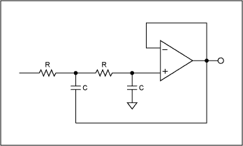
Figure 1. Equal component value, Sallen-Key lowpass filter.
However, there are some drawbacks to this topology. First, it is very limited in the maximum Q value one can obtain and thus is not recommended for applications that need a high Q. The Q of a filter is the "quality" factor, which basically gives the ratio of energy stored to energy dissipated at resonance. High Q filters allow very sharp filter roll-offs. In terms of the s-plane, high Q filters have their poles located closer to the jw axis. Keep in mind that as long as the poles are on the left-hand side of the jw axis, the device is theoretically stable. As the poles get closer and closer to the jw axis, the stability decreases. Now back to the Q factor. The Q factor is often used when selecting or designing a band-pass filter. The inverse of the Q is the damping factor, which is more relevant in low-pass and high-pass applications. For a single op-amp Sallen-Key filter, the Q is typically around 5 or so.
Another drawback is that the gain of this circuit is relatively low (-3Q) compared to the minimum required open loop gain of the amplifier (90Q²). This means that the GBW product of the amplifier must be significantly higher than the maximum cutoff frequency of the filter resulting in a higher performance amplifier than expected to ensure it does not limit adversely affect the filter response.
To obtain a slightly higher Q, lets move to the multiple feedback infinite gain architecture shown in Figure 2. This topology again requires a single amplifier and provides for Q's in the range of 25. Using this topology, the gain is (-2Q²) is still relatively low compared to the amplifiers GBW product (20Q² at resonance), but not nearly as low as the Sallen-Key approach.
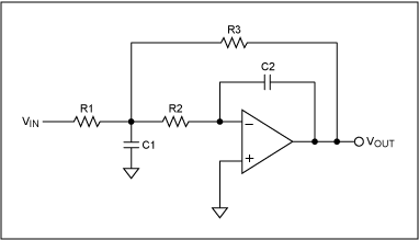
Figure 2. Infinite-impulse, multiple feedback lowpass filter.
Note however, this topology inverts the signal and also note that the gain and Q value are inextricably related as with the Sallen key. Both the Sallen Key and the multiple feedback architectures also are fairly sensitive to external component variation. To move to a more robust filter, we now consider the 3 and 4 op amp state-variable and biquad architectures. State Variable BiquadFigure 3 shows the basic architecture of the 3 amplifier state variable Biquad. It comprises a summing node followed by two integrators. This architecture is quite versatile in that it gives a high-pass, band-pass and low-pass output, but it also allows independent control of fc, and the Q.
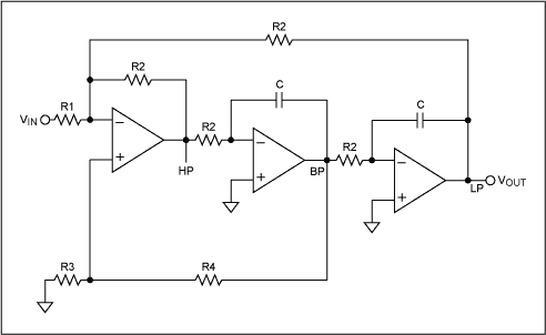
Figure 3. Three amplifier state-variable biquad.
By adding a 4th amplifier, independent control of the Q and gain is realized (Figure 4). The state variable is ideal for high Q circuits. Q's of 500 or more are easily attainable with proper filter design. And unlike the single op amp architectures, the open loop gain (3Q) need only be slightly higher than the filter's output gain (Q), and the low-pass gain is Q, which reduces the requirements on the op amps GBW (note that for the Sallen-Key, the op loop gain had to be a minimum of 90Q² which with a Q of 500 would be 22.5MHz.
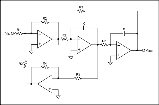
Figure 4. Biquad state variable filter with independent control of q /damping.
Of the topologies discussed thus far, the start variable is the least sensitive to component variations. It also has another unique attribute: as the frequency fc changes, the Q and percentage bandwidth remains constant. That is, as you shift fc in the frequency domain, the Q value remains the same, but the bandwidth of the filter decreases as you increase fc and increases as you decrease fc. The percentage bandwidth is defined as 100% × ((FU - FL)/(√ FU × FL) where FU is the upper 3dB bandwidth point, FL is the lower 3dB bandwidth point and √FU × FL is fc.
The major drawback to the state-variable design is the use of 3 or 4 amplifiers. This is especially true for power sensitive applications. The design itself is fairly straightforward due to the plethora of filter software and filter design cookbooks available. However, when working with high Q's one must be very careful with layout and component selection. This is because high Q circuits have a tendency to exhibit instability with slight component mismatch. They also are more likely to oscillate due to this instability. The Biquad FilterLastly, we look at the Biquad filter (Figure 5). It is quite similar to the state-variable biquad shown above. However, it comprises an integrator followed by an inverter and then another integrator. Note that this subtle change provides a circuit that behaves different than the state variable filter.
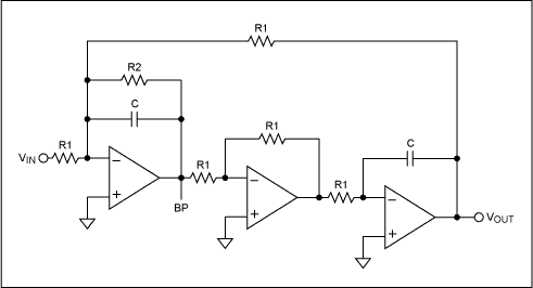
Figure 5. Biquad filter.
The big difference is that for a biquad, as fc changes, the bandwidth stays constant, but the Q value changes. Thus, if you change fc in the frequency domain, as fc increases, the Q value increases and as fc decreases, the Q value also decreases. Other than this difference, the biquad behaves like the state variable. It allows very high Q values, it can be configured in a 3 or 4 amplifier configuration, and it too is less sensitive to external component variations. The 3 and 4 amplifier circuits draw more power, and usually require more design time, especially when multiple stages are cascaded to obtain a steeper filter roll-off response. In addition, it is more costly as a single amplifier is cheaper than a quad. From a performance point of view, it is much better, and that is the trade-off that must be made.
You can design your filter using the techniques above using op amps. Maxim has a wide variety of high-speed and high-precision op amps that can be used in filter designs. An alternative, if you prefer not to do the design yourself, is the MAX274/275 integrated filters. These single chip solutions are configured as 8th order (8 pole) and 4th order (4 pole) filters, respectively, that are made up of 2nd order building blocks.
These continuous time filters are biquad in architecture and provide low-pass and band-pass outputs. A filter software program is also available to help simplify the design process. Maxim also has a number of other biquad and state variable filters to meet other performance needs.
MAX274, MAX275 QuickView data sheet
Maxim Filter Design Software (.zip file, 487K)
欢迎分享,转载请注明来源:内存溢出

 微信扫一扫
微信扫一扫
 支付宝扫一扫
评论列表(0条)