
In the generic example of Figure 1, a digital baseband signal is sampled by the DAC. The DAC's frequency response is not flat and attenuates the analog output at higher frequencies. At 80% of fNYQUIST, for instance (fNYQUIST = fS/2), the frequency response is attenuated by 2.42dB. That loss is unacceptable for some broadband applications requiring a flat frequency response. Fortunately, however, several techniques are available for coping with the non-flat frequency response of a DAC. These include increasing the DAC's update rate, as well as using interpolation techniques, pre-equalization filtering, and post-equalization filtering—all of which reduce or eliminate the effects of the sinc rolloff.
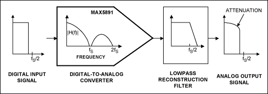
Figure 1. The non-flat frequency response of a DAC attenuates the output signal, especially at high frequencies.
Understanding DAC Frequency ResponseTo understand the non-flat frequency response of a DAC, consider the DAC input as a train of impulses in the time domain (Figure 2a), and a corresponding spectrum in the frequency domain (Figure 2b). An actual DAC output is a "zero-order hold" (Figure 2c) that holds the voltage constant for an update period of 1/fS. In the frequency domain, this zero-order hold introduces sin(x)/x distortion (also called aperture distortion)[1]. As shown in Figure 2d, the amplitude of the output-signal spectrum is multiplied by |sin(x)/x| (the sinc envelope), where x = πf/fS. The resulting frequency response is given in equation 1 and plotted in Figure 3. Thus, aperture distortion acts like a LPF that attenuates image frequencies, but also attenuates the desired in-band signals.
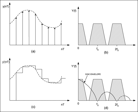
Figure 2. The ideal output from a DAC is a train of voltage impulses in the time domain (a), and a series of image spectra in the frequency domain (b). Actual DACs use a zero-order hold to hold the output voltage for one update period (c), which causes output-signal attenuation by the sinc envelope (d).
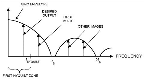
Figure 3. This representation of a DAC output in the frequency domain shows that the desired signal is generally within the first Nyquist zone, but many image signals are present at higher frequencies.
The sin(x)/x (sinc) function is well known in digital signal processing. For DACs, the input is an impulse and the output is a constant-voltage pulse with update period of 1/fS (the impulse response), whose amplitude changes abruptly in response to the next impulse at the input. The DAC's frequency response is obtained by taking the Fourier transform of the impulse response (a voltage pulse). The Fourier transform of a pulse takes the general form of H(f) = sin(pf/fS)/(pf/fS)[2]:

As shown in Figure 3, the desired signal frequency in the first Nyquist zone is reflected as a mirror image into the second Nyquist zone between fS/2 and fS, but its amplitude is attenuated by the sinc function. Image signals also appear in higher Nyquist zones. In general, these image frequencies must be removed or attenuated by a lowpass (LPF) or bandpass filter (BPF), often called reconstruction filters. Such filters are analogous to the antialiasing filter often required with an analog-to-digital converter.
As the DAC output frequency approaches its update frequency fS, the frequency response approaches zero or null (Figure 3). Therefore, the DAC's output attenuation depends on its update rate (see equation 1). The 0.1dB frequency flatness is about 0.17fNYQUIST, where fNYQUIST = fS/2. As the output frequency approaches fS/2, so does the first image frequency (Figure 3). As a result, the maximum usable DAC output frequency (for systems in which the image frequency is removed by filtering) is about 80% of fNYQUIST.
The first image frequency is fIMAGE = fS - fOUT. At fOUT = 0.8fNYQUIST, fIMAGE = 1.2fNYQUIST, leaving only 0.4fNYQUIST between frequency tones for the filter to remove the image. Output frequencies higher than 80% of fNYQUIST make it difficult for a filter to remove the images, but the reduction in usable frequency output allows for realizable designs of the reconstruction filter.
Increase the Update Rate?At 80% of fNYQUIST, the output amplitude is attenuated by 2.42dB. For broadband applications requiring a flat frequency response, that attenuation is unacceptable. Because the DAC's output attenuation depends on its update rate, you can minimize the effect of sinc rolloff and push the 0.1dB flatness to a higher frequency simply by increasing the converter's update rate and keeping the input-signal bandwidth unchanged.
Increasing the DAC's update rate not only reduces the effect of the non-flat frequency response, it also lowers the quantization noise floor—expressed as noise spectral density for most DAC data sheets—and loosens requirements for the reconstruction filter. Drawbacks include a higher cost for the DAC, higher power consumption, and the need for faster data processing. The benefits of higher update rates are so important, however, that manufactures are driven to introduce interpolation techniques. Interpolating DACs offer all the benefits of higher update rates, while keeping the input data rate at a lower frequency.
Interpolate?Interpolation DACs include one or more digital filters, which insert a sample after each existing data sample. In the time domain, the interpolator stuffs an extra data sample for every data sample entered, with a value interpolated between each pair of consecutive data-sample values. The total number of data samples increases by a factor of two, so the DAC must update twice as fast.
The MAX5895[3], for example, incorporates three interpolation stages to achieve an 8x interpolation (the DAC's update rate is eight times the data rate). This technique increases the update rate while keeping the data rate a lower frequency. In the frequency domain, the sinc frequency response is moved out by a factor of eight as well and the effective image frequency shifts out by a factor of eight, which loosens requirements for the reconstruction filter.
Pre-Equalizing?Increasing the update rate reduces but does not eliminate the effect of sinc-frequency rolloff. If you are already using the fastest DAC available, you must choose other techniques to reduce the DAC's frequency rolloff. It is possible, for example, to design a digital filter whose frequency response is the inverse of the sinc function—i.e., 1/sinc(x). In theory, such a pre-equalization filter cancels the effect of the sinc frequency response, producing a perfectly flat overall frequency response. A pre-equalization filter first filters the digital input data to equalize the baseband signal, and then sends data to the DAC. By removing the sync attenuation at the DAC output, it allows the original signal to be reconstructed without attenuation (Figure 4a).
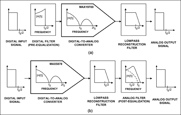
Figure 4. A pre-equalization digital filter is used to cancel the effect of sinc rolloff in a DAC (a). As an alternative, you can use a post-equalization analog filter for the same purpose (b).
Any digital filter whose frequency response is the inverse of the sinc function will equalize the DAC's inherent sinc frequency response. Because the sinc frequency response is not 1st-order, however, a finite-impulse response (FIR) digital filter is preferred[1]. Frequency-sampling techniques are used in designing the FIR filter. Assuming the signal is in the first Nyquist zone, the frequency response (H(f)) is sampled from DC to 0.5fS (Figure 5). Using the inverse Fourier transform, the frequency sample points (H(k)) are then transformed to impulse responses in the time domain. The impulse response coefficients are:

where H(k) and k = 0, 1, ... N-1 represent the ideal or targeted frequency response. The quantities h(n) and n = 0, 1, ... N-1 are the impulse responses of H(k) in the time domain, and
 = (N-1)/2. For a linear-phase FIR filter with positive symmetry and even N, h(n) can be simplified using equation 3[1]. For an odd value of N, the upper limit in the summation is (N-1)/2.
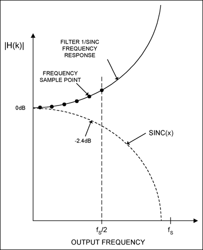
Figure 5. A digital pre-equalization filter is designed by sampling the inverse sinc frequency response from DC to fS/2.
Increasing the number of frequency sample points (N) of H(k) produces a frequency response closer to the targeted response. A filter with too few sample points reduces the effectiveness of the equalizer by producing a larger deviation from the targeted frequency response. On the other hand, a filter with too many sample points requires more digital processing power. A good technique is to use a large N for computing h(n), truncate h(n) to a small number of points, and then apply a window to smooth h(n) and produce an accurate frequency response.
The filter shown in Figure 6 uses N = 800 to compute h(n). You then truncate h(n) to only 100 points, and apply a Blackman window to h(n). The frequency response for the combined FIR filter and DAC sinc response (top curve in Figure 6) exhibits 0.1dB flatness nearly up to the Nyquist frequency (i.e., to about 96% of fNYQUIST, where fNYQUIST = fS/2)). In contrast, the uncompensated DAC response (bottom curve) maintains 0.1dB flatness only to 17% of fNYQUIST. Because the filter gain is greater than unity, you must take care that the filter's output amplitude does not exceed the DAC's maximum-allowed input level.
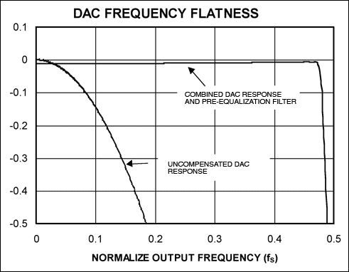
Figure 6. The FIR filter designed in Figure 5 equalizes the DAC's sinc response and achieves 0.1dB flatness up to 96% of fNYQUIST.
After obtaining the impulse-response coefficients using equation 3, you can implement the FIR filter using a standard digital-processing technique. That is, h(n) filters the input signal data x(n) as in equation 4:

Dynamic performance for the compensated DAC is lower than that of the uncompensated DAC, because higher gain at the higher input frequencies requires that you intentionally lower the signal level to avoid clipping the input. Assuming the input is a single tone between DC and fMAX (< fS/2), the attenuation depends on fMAX:

where VIC is the input voltage for the compensated DAC, and VREF is the reference voltage. If, for example, the maximum anticipated input frequency is fMAX = 0.8fNYQUIST, the DAC input must be attenuated by noise and thermal noise. The maximum SNR for the compensated DAC is constant and independent of frequency, but it depends on the maximum anticipated output frequency:

where VOC is the output amplitude.
For the uncompensated DAC, the output signal is attenuated by the sinc envelope:

Noise power for the uncompensated DAC is same as for the compensated DAC. Thus, the maximum uncompensated DAC SNR is

Degradation of the compensated DAC SNR is found by dividing the SNRs:

Degradation of the compensated DAC SNR is frequency dependent, unlike that of the uncompensated DAC. Degradation is worse at lower frequencies than at fMAX.
Post-Equalizing?Another method for equalizing the DAC's sinc frequency response over the output frequency band of interest is to add an analog filter whose frequency response is approximately equal to the inverse of the sinc function. Many such analog equalizing filters have been designed to equalize transmission lines and amplifiers. These techniques can be adapted to reduce the effect of a DAC's unwanted sinc response. The post-equalizing filter is inserted after the DAC's reconstruction filter (Figure 4b).
The simple active equalizer shown in Figure 7a is used for this application. For a given bandwidth, R1, R2, and C1 are chosen so the analog equalizer's frequency response cancels the DAC's sinc frequency response. SPICE-simulation software can help optimize the frequency flatness for a given application. The frequency response for a typical analog equalizer (Figure 7b) shows that 0.1dB flatness extends to more than 50% of fNYQUIST. Without the post-equalizing filter, 0.1dB flatness extends only to 17% of fNYQUIST. Note that the maximum circuit gain in Figure 7a is (1+R1/R2).
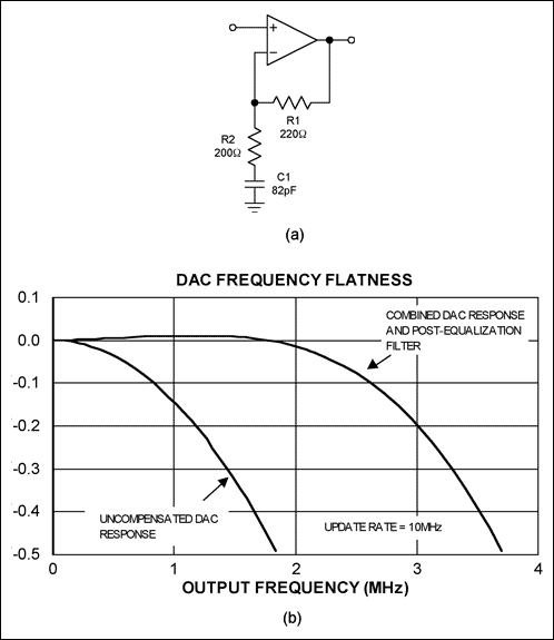
Figure 7. Used to reduce the effects of DAC sinc rolloff, this simple active analog equalizer (a) increases the 0.1dB flatness from 17% to 50% of fNYQUIST (b).
A post-equalization filter affects the DAC's SNR because it amplifies the noise at higher frequencies. Assuming the noise in an uncompensated DAC is limited by quantization noise, the output signal and noise together are attenuated by the sinx/x envelope. With a post-equalization filter, however, the output signal amplitude and noise density are constant over frequency (assuming perfect compensation). Output noise for the compensated and uncompensated DACs is obtained by integrating the noise power from near DC to fNYQUIST:
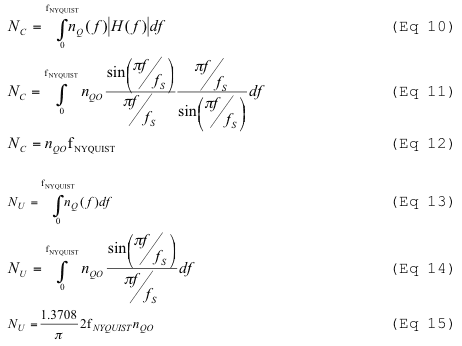
where H(f) is the frequency response for the post-equalization filter, nQ(f) is the noise power density, nQO is the unattenuated quantization noise density near DC, and NC and NU are the total noise power of the compensated and uncompensated DACs, respectively. Maximum SNR is normalized to the reference voltage VREF. Remember that fNYQUIST equals fS/2. The SNRs are then:
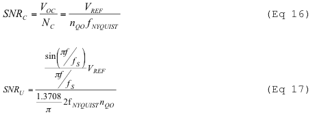
Again, dividing the two SNRs gives the compensated SNR in terms of the uncompensated SNR. The maximum SNRC degrades at lower frequencies, but improves at higher frequencies:

Thus far, the DAC's reconstruction filter is assumed to be an ideal LPF: its frequency response is flat to fNYQUIST, and then drops abruptly to zero. In practice, a reconstruction filter also adds rolloff near its cutoff frequency. Accordingly, the pre- and post-equalizing techniques discussed previously can serve an additional purpose—that of equalizing any rolloff in the reconstruction filter.
SummaryThe effect of a DAC's inherent sinc frequency response attenuates the output signals, especially at higher frequencies, and the resulting non-flat frequency response reduces the maximum useful bandwidth in broadband applications. Higher update rates flatten the frequency response, but higher update rates also increase the DAC's cost and complexity.
The pre-equalization technique, which employs a digital filter to process the data before sending it to the DAC, offers 0.1dB frequency flatness to 96% of fNYQUIST (fNYQUIST = fS/2), but requires additional digital processing. (For comparison, an uncompensated DAC offers 0.1dB flatness only to 17% of fNYQUIST.) Another technique adds a post-equalization analog filter to equalize the DAC's output and achieves 0.1dB flatness to 50% of fNYQUIST, but requires additional hardware. Both compensation techniques offer reduced SNR at low output frequencies.
A similar version of this article appeared in the April 13, 2006 issue of EDN magazine.
References
- Emmanuel C. Ifeachor, et. al., Digital Signal Processing, Addison-Wesley, 1993.
- James W. Nilsson et al, Electric Circuits, 5th edition, Reading, Massachusetts, Addison-Wesley, 1996, p. 833.
- MAX5895 data sheet, Maxim Integrated Products, Inc.
欢迎分享,转载请注明来源:内存溢出

 微信扫一扫
微信扫一扫
 支付宝扫一扫
评论列表(0条)