OverviewIn 1975 the Federal Communications Commission (FCC), the government agency that regulates radio frequency (RF) emissions in the United States, enacted new regulations called FCC Part 15. These were not directed at controlling equipment such as radio and TV transmitters, or aircraft-navigation and emergency beacons that deliberately radiate high-power RF energy. Instead, these regulations sought to control equipment that did not deliberately radiate RF energy such as televisions, automobiles, and low-power, unregulated RF radiators such as walkie-talkies and electronic remote controls.
A good example of the motivation behind these regulations occurred years ago at Dallas/Fort Worth Airport. Pilots, during takeoffs and landings, reported loss-of-control situations with recently developed electronic flight-control systems. The FCC traced the cause to interference from remote-controlled garage-door openers in homes in the surrounding suburban areas. The Part 15 regulations addressed this problem by requiring that all electronic equipment sold in the U.S. be tested and certified to ensure against radiated RF energy that could cause malfunctions in other electronic devices.
During the 1980s and 1990s, electronic devices from microwave ovens to cell phones proliferated. Cross interference between these devices became a problem. Microwave ovens interfered with pacemakers, while cable modems interfered with cordless phones. Similarly, computer monitors radiated enough RF energy that interfered with most other electronic equipment in their vicinity.
The FCC and other regulatory bodies such as the Electro Magnetic Compatability (EMC) agency in Europe, responded with tighter regulations regarding these emissions in all electronics. In the U.S., FCC Part 68 regulated industrial and commercial electronic devices. Part 68, Class A involved equipment used in an industrial environment while Part 68, Class B addressed consumer products. This article will concentrate on Class B electronics only.
Reducing Radiated EmissionsRadiated emissions occur in any piece of electronics that has a changing electrical signal radiates emissions. In the case of the PC motherboard with a clock running at a certain frequency, it will radiate RF energy tightly centered on the frequency of the master oscillator.
Definitions:Radiated susceptibility is the sensitivity of a piece of electronic equipment to interface from outside RF energy sources.
Radiated emissions are RF energies unintentionally radiated by a piece of electrical equipment, such as a PC or monitor, which might have some impact on another piece of electrical equipment.
EMC (Electromagnetic Compatibility): The ability of electronic equipment to be a "good electromagnetic neighbor": It neither causes, nor is susceptible to, electromagnetic interference (within the limits of applicable standards). See: Glossary definition
EMI (Electromagnetic Interference): Unwanted noise from electromagnetic radiation. See: Glossary definition
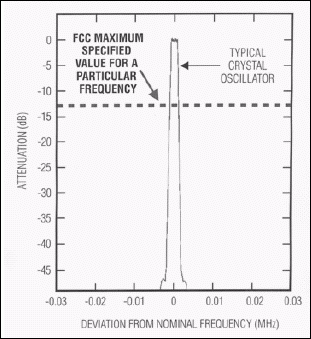
If the radiated RF energy from a PC motherboard is measured, radiation spikes at the oscillator's center frequency are present (Figure 1). FCC requirements for consumer products (FCC Part 68, Class B) require that radiated emissions must be below a specified maximum value at any given frequency.

Figure 1. Comparison of typical crystal oscillator emissions to the FCC maximum.
Ironically, the standards do not reduce the total amount of energy radiated, only the peak amount of energy that may be radiated at any one frequency.
A traditional, older method of reducing radiated emissions involved containment. A personal computer used its grounded steel cabinet as a shield to intercept and dissipate the energy radiated by the motherboard. Plastic cabinets used in enclosed electronic devices were often coated with a metallic layer and grounded to achieve the same purpose. As electronics proliferated and became increasingly smaller, containment techniques became more difficult to accomplish. Higher clock speeds of electronics included higher harmonic frequencies that forced the designer to use techniques such as shielding, EMI filtering, and careful circuit layout to reduce radiated emissions. This approach became costly and more difficult as consumer electronics shrunk. A new method was needed to reduce these peak-radiated emissions.
By spreading or dithering the frequency of a system's clock, radiated emissions can be 'smeared' over a narrow spectrum, reducing the peak-radiated emissions at any one frequency. This simplifies the design engineer's task and reduces the cost of the manufactured product. Over the past few years, this use of spread-spectrum clock oscillators to reduce peak-radiated emissions gained popularity in everything from PC motherboards to printers.
History of Spread SpectrumDuring WWII, the U.S. Navy was having problems with radio-controlled torpedoes that were being "jammed" by high-strength RF signals tuned to the same frequency as the transmitting radio. This is an example of radiated susceptibility. In August 11, 1942, Hedy Keisler Markey and George Antheil were granted U.S. Patent Number 2,292,387 for a "Secret Communication System" that solved this problem. The device used a mechanism to rapidly switch between frequencies on the transmitter (this technique is similar to what is now called frequency hopping). A similar device on the receiver in the torpedo switched between the same frequencies and captured the transmitted signal. The signal controlling the torpedo never remained at any individual frequency long enough to be jammed by an external RF signal at a single frequency. A more sophisticated version of this technique was used half a century later to reduce interference in communication devices such as cellular and cordless phones.
Using Spread-Spectrum Technology to Reduce Radiated EmissionsWhile the term spread spectrum is used in techniques for reducing radiated emissions in consumer electronics, the application is different than that used in devices such as cordless phones. In the cordless phone the operating frequency of both the transmitter and receiver are swept over a band of frequencies in unison, reducing the effect of outside radiation at any one frequency.
The use of spread-spectrum technology for RF reduction in unintentional transmitters in consumer products such as PCs, involves sweeping the clock that drives the PC over a band of frequencies. Thus, any radiated emissions are spread over the band, and only a small amount of the total energy is radiated at any one frequency. This reduces the peak energy at that frequency to below the FCC-mandated levels.
The above method uses a signal applied to the oscillator that moves the frequency as a function of the signal level. In its simplest form, a triangle signal is applied to an oscillator circuit, which varies the oscillator's frequency as a function of the triangle amplitude (Figure 2). Actually, the shape of the signal applied can vary slightly from this triangle example.

Figure 2. Oscillator dither.

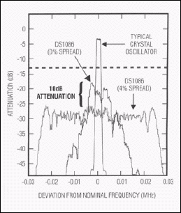
Figure 3. Clock spectrum dither comparison.
Figure 3 shows the radiated emission output of a dithered DS1086 oscillator compared to that of the crystal oscillator shown earlier. The graph shows DS1086 with both a 0% dithered output and a 4% dithered output. The graph demonstrates how the "spreading" of an oscillator's frequency reduces the peak radiated emissions at any particular frequency to below the FCC-mandated levels. The dither signal's frequency is selected so that it is much lower than the frequency of the oscillator it is dithering. Consequently, electronics driven by the oscillator are not affected by rapid frequency changes. It is also selected to be above the audible range of frequencies so that audible noise is not generated by reactive components in the circuitry, such as capacitors and inductors. The graph above shows the spectrum of radiated energy of a crystal oscillator, a "0%" spread on an EconOscillator™ and a 4% spread on an EconOscillator. A 2% spread is available but not shown. The "0%" spread is actually approximately a ½% to 1% spread due to dither characteristics intrinsic to the architecture of the EconOscillator.
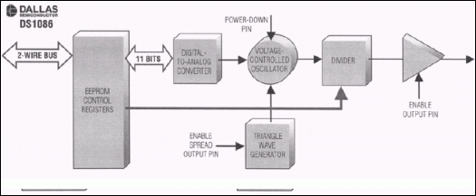
The DS1086The DS1086 is an EconOscillator designed to induce dither in the oscillator output, reducing radiated emissions in systems from printers to gaming consoles. The device consists of a programmable 66MHz to 133MHz clock-frequency generator tunable in 10kHz increments through a 2-wire interface. This, in conjunction with a prescaler that divides the master oscillator frequency by 2X (where x = 0 to 8), provides for a broad selection of frequencies ranging from 260kHz to 133MHz. Input pins provide control for gating the clock output, turning on and off the dither, and disabling the master oscillator. Three dither options are selectable: "0%", 2%, and 4%. Unlike low-EMI oscillators from other manufacturers, the DS1086 requires no external crystal or clock reference for operation, making it the smallest footprint, low-EMI clock available (Figure 4). It is available in an 8-pin SO package.

Figure 4. The DS1086 Spread Spectrum EconOscillator.
Like other EconOscillators, the DS1086 uses a precisely controlled digital-to-analog converter (DAC) in conjunction with a calibrated voltage-controlled oscillator (VCO) to generate its center-frequency output. Frequency dithering is injected into the output frequency by summing a triangle-wave voltage signal into the VCO input. The triangle wave's amplitude determines the percentage dither in the output clock. This can be set at 0%, 2%, or 4%, depending on the application. Note that the 0% dither selection has approximately 1% dither that is intrinsic to the architecture of all EconOscillators. Even standard EconOscillators with this characteristic have up to a 10dBm reduction in radiated spectrum when compared to a crystal oscillator, without any additional circuitry.
SummaryFCC radiated emission compliance standards for consumer electronics have made engineering efforts increasingly difficult for the circuit designer. Faster clock speeds include even higher harmonic frequencies that force the designer to use shielding, EMI filtering, and careful circuit board layout to reduce radiated emissions. By adding frequency modulation (FM) or "dithering" to the center frequency of a system's clock, radiated emissions can be spread over a narrow spectrum, reducing the peak-radiated emissions at any one frequency, satisfying the FCC requirements.
This simplifies the designer's engineering task and can substantially reduce the cost of the finished product. In the past few years, the use of spread-spectrum clock oscillators has gained popularity. The characteristics of the clock are a relatively precise short-term stability of the frequency, usually on the order of 200ppm to 300ppm. The longterm frequency stability is swept over frequency values ranging from ½% to 4&% of the oscillator's center frequency.
Links to the DS1086 data sheet, application notes and an online interactive frequency calculator can be found at the following link:
http://www.maxim-ic.com/quick_view2.cfm/qv_pk/3610
欢迎分享,转载请注明来源:内存溢出

 微信扫一扫
微信扫一扫
 支付宝扫一扫
评论列表(0条)