
A similar version of this arTIcle appeared in the July 14, 2010 issue of EE TImes magazine.
The input-voltage range for a typical voltmeter IC is usually ±200mV, with precision of 3½ or 4½ digits. A sigma-delta panel-meter IC from Maxim (MAX1499) is no excepTIon, but you can easily double the range (to ±400mV), and extend the precision to 4¾ digits (±40000 counts).
Adjacent to the internal 20-bit ADC and 7-segment display driver, the MAX1499 includes an SPI™ interface that allows access to the ADC result, and also offers full control over the LED display. A microcontroller can easily use this interface to read the ADC result and control what is shown on the display.
Circuitry for doubling the input range is as simple as a resistor divider that cuts the signal in half, allowing the IC's input-voltage range to remain ±200mV. Instead of VIN, the ADC now measures VIN/2. You can easily compensate this factor of two by shifTIng the result one bit to the left (digital multiplication by 2).
The ADC resolution is 20 bits, which is more than enough to support 4¾-digit precision. (Normally, the IC obtains 4½ digit precision using only 16 of the 20 available bits.) Figure 1 shows how the data is rearranged. The 17th bit is used to fill the gap caused by the multiplication by 2.
The resistor divider adds gain error, so you should choose resistors whose accuracy meets the requirements of your application.
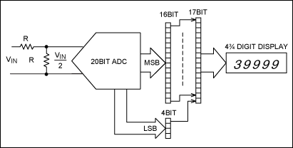
Figure 1. The range of this panel-meter circuit is doubled by scaling the input signal, and its precision is doubled by using more of the available bits.
A 7-segment display driver internal to the panel-meter IC drives a common-cathode LED display, using a multiplexing scheme to drive one digit at a time. Unfortunately the driver is optimized for driving 4½-digit displays. That means that the first (most significant) position can only show a "half digit" of +1 or -1 (Figure 2).
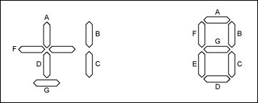
Figure 2. Seven-segment displays include half digits (left) and full "1" digits (right).
Signals via the SPI interface can switch all segments in the display on and off individually, except for those in the first digit. Segments B and C (which form "1") can only be switched on or off together. The same is true for segments A, F, and D (which form "+"). Segment G (which forms "-") is on when segments A, F, and D are off, and vice versa. To upgrade this display to 4¾ digits, you must ensure that the first digit position can show "1," "2," "3," or a blank (Figure 3). From the figure it is clear that segment F is never used, so you need only control six of the segments.
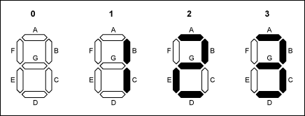
Figure 3. In the four possible states of a ¾-digit display, segment F is always off.
If the ½-digit display is replaced by a full "1-digit" display, and control lines for the F and G segments are swapped, all segments but F are lit when the "1" and "+" signs are activated (Figure 4). The E segment is not used in the ½-digit display, and if left connected is on by default. Adding switches in the form of low-cost NPN transistors enables a microcontroller to turn each segment on and off via a few GPIO pins, producing a display of blank, "1," "2," or "3." The complete circuit is shown in Figure 5.
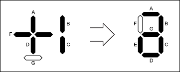
Figure 4. To convert a ½-digit display to a full "1-digit" display, swap the control lines to the F and G segments.
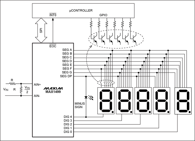
Figure 5. Complete 4¾-digit panel-meter circuit.
The end of conversion (EOC\) signal connects to an external interrupt on the microcontroller. When a new value appears, the microcontroller reads it through the SPI port and multiplies it by 2. It then determines which segments to illuminate (switch on) by using the SPI port to set correct values in the display registers. External transistor switches are then set via the GPIO pins to create the desired character.
In front of the first digit you can use a rectangular LED as a minus sign, controlled by the signal of an unused decimal point. Any microcontroller with an external interrupt pin, an SPI interface, and enough GPIOs is acceptable for this application. The test setup includes a MAX1499 panel-driver IC on the display board, controlled by a low-power RISC microcontroller (MAXQ610) on its own evaluation board (Figure 6). Firmware is available for download.
欢迎分享,转载请注明来源:内存溢出

 微信扫一扫
微信扫一扫
 支付宝扫一扫
评论列表(0条)