
To maximize signal swing, the output of a single-supply op amp is usually biased at half the supply voltage (Figure 1a). For ground-referenced loads, however, this configuration causes maximum power dissipation in the IC.
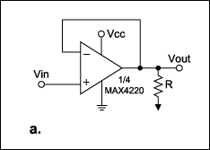
Figure 1a. A single-supply op amp biased at mid-VCC.
The solution is simple and effective: connect a pullup resistor, with value equal to the load resistor, between the output and the positive supply voltage (Figure 1b). This addition enables the op amp to operate at higher ambient temperatures and drive lower-resistance loads, limited only by its maximum ratings for output voltage and current (rather than the package power dissipation).
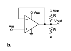
Figure 1b. The power dissipated in Figure 1a is reduced by adding a load-value pullup to VCC.
For example, consider the MAX4220 quad op amp, in which each output drives a 30Ω resistor to ground. For VCC = 5V, the device exceeds its package power rating. Connecting 30Ω pullups at each output, however, minimizes the IC's power dissipation because each op-amp's output current is zero. Power is now dissipated in the pull-up resistors and not in the op amps.
Calculating power dissipation for the op amp in Figure 1a is straightforward:
PDC = (VCC - VOUT) VOUT/R.
Solving the differential equation dPDC/dVOUT = 0 for VOUT shows that the op amp's maximum power dissipation (VCC²/4R) occurs when VOUT = VCC/2.
The corresponding power calculation for the circuit with load and pullup resistors (Figure 1b) is simpler if you convert the load circuit to its Thevenin equivalent (Figure 1c):
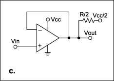
Figure 1c. A Thevenin-equivalent circuit aids analysis.
PDC = (VCC - VOUT)(VOUT - ½VCC)/½R (for VOUT ≥ ½VCC),
and PDC = VOUT(½VCC - VOUT)/½R (for VOUT ≤ ½VCC).
Again, solving dPDC/dVOUT = 0 for these two equations shows that the maximum power dissipation (VCC²/8R) occurs for VOUT = ¾VCC and for VOUT = ¼VCC. Note that this maximum power level is only half of that with no pullup resistor. The amplifier with no pullup resistor delivers maximum output current at the VCC/2 quiescent point, but with a pullup resistor (Figure 2) the op amp delivers no output current at all!
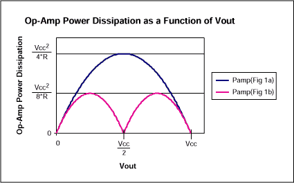
Figure 2. The op amp's maximum power dissipation in Figure 1a is twice that of the op amp in Figure 1b.
Similar power advantages accrue for AC applications. Consider a sinusoidal signal superimposed on a DC level of VCC/2: VOUT = ½VCC + Vpsinωt, where Vp is the peak value of the sinusoid. The resulting waveforms are shown in Figure 3. The simplest method for calculating power dissipation in the op amp is to solve a power-balance equation, in which supply power equals the sum of power dissipated in the load and in the op amp. Thus, the op amp dissipation equals supply power minus load power.
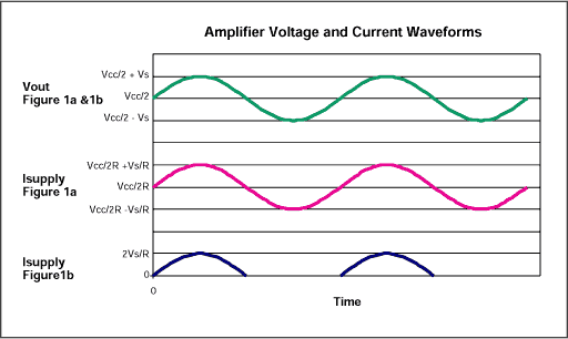
Figure 3. These waveforms illustrate the op amp voltage and current relationships in Figures 1a and 1b.
For the case of Figure 1a, supply power equals the average supply current (VCC/2R) times VCC, i.e., VCC²/2R. Power in the load is the sum of the DC and AC components: (1/R)(½VCC)² + (1/R)(Vp/2½)². Thus, supply power minus load power for the Figure 1a circuit is PAC = VCC²/4R - Vp²/2R, as shown in Figure 4.
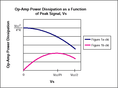
Figure 4. Power dissipation in the op amp of Figure 1a is always far greater than that of 1b.
For the Figure 1b circuit, supply power equals the average supply current 2Vp/πR times VCC as shown in Figure 3, i.e., 2VpVCC/πR. Power in the load is 2(Vp/2½)²/R, and the supply power minus load power is PAC = 2VCCVp/πR - Vp²/R as shown in Figure 4. Solving the equation dPAC/dVp = 0 for Vp shows that the Figure 1b op amp's maximum power dissipation (VCC/π)²/R) occurs when Vp = VCC/π.
Thus, you can minimize the power dissipation in a single-supply op amp, driving a ground-referenced load, by adding a single external resistor.
A similar version of this article appeared in the July 23, 2001 issue of Electronic Design magazine.
欢迎分享,转载请注明来源:内存溢出

 微信扫一扫
微信扫一扫
 支付宝扫一扫
评论列表(0条)