引言DS1WM1-Wire总线主机内部生成1-Wire时序和控制信号,无需CPU产生逐位控制时序。该控制功能使系统程序设计人员能够使用API函数进行程序开发。DS1WM API采用ANSI C语言编写,可以为多种支持ANSI C的微处理器平台所用。以下例程介绍了如何在网络中识别、选择1-Wire从设备,并与其进行通信。

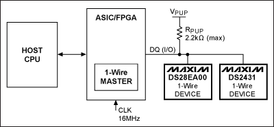
图1. 1-Wire网络总线示例电路
图1所示的电路配置适用于以下所有示例程序。主机CPU利用DS1WM与带有链路模式和GPIO的1-Wire数字温度传感器DS28EA00以及1-Wire 1Kb EEPROM DS2431进行通信。示例程序重点演示API,而非从设备功能。16MHz的系统时钟通过CLK引脚提供1-Wire主机时序。1-Wire主机的端口引脚需要映射到应用微处理器的引脚。API文件DS1WM.h中包含了引脚映射功能。API头文件中的MaxNumberDevices宏必须更改为实际可能的最大器件数。DS1WM.c API文件中的ReadByteFromRegister和WriteByte2Register函数也需要进行修改,以便正确触发微处理器端口。VPUP电压典型值为5.0V,RPUP不大于2.2kΩ。 概述通过Maxim支持中心,可以申请免费的DS1WM和API。下面讨论了初始化和1-Wire复位控制的DS1WM代码。此外还提供了一个示例,用于演示如何使用DS1WM ROM搜索引擎确定每个器件的唯一注册码(ROM ID)。使用存储的注册码以及家族码,可以识别每个1-Wire从设备,并通过匹配ROM命令进行访问。家族码列表,请参见应用笔记155:“1-Wire®软件资源指南”。DS28EA00示例演示了如何进行温度转换。第二个示例给出了高速读写DS2431暂存器的两种方法。
总线主机基本 *** 作微处理器通过触发复位引脚初始化DS1WM,API接口执行所有1-Wire通信。示例程序通过调用DS1WM API函数进行工作。由于响应中断时会改变微处理器代码,因此后续示例中采用轮询方式替代中断方式通信。
后续的示例程序中用到了表1所示的1-Wire *** 作。
表1. 1-Wire *** 作
初始化通过初始化DS1WM,启动主机,提供正确的1-Wire总线时序。主机将数值16 (代表频率值)传递至SetClockFrequency函数,将0x90h写入时钟分频寄存器(请参见DS1WM数据资料)。中断使能寄存器设置为0x00h,防止INTR引脚产生中断。上电时,接收缓存可能包含无效值,因此在发送1-Wire命令之前,最好对接收缓存进行清理。启动时对中断寄存器和接收缓存器的读 *** 作将清除其中的各个位。
//----------------------------------------------------------------------------------------------------
//Start of initialization example

SetClockFrequency(16);                  //Set clock frequency to 16MHz (power-on default)
InterruptEnableRegisterWrite(0x00);     //Clear interrupts

//Flush receive buffer
InterruptRegisterData = InterruptRegisterRead();
ReceiveBufferRead();

//End of initialization example
//----------------------------------------------------------------------------------------------------
1-Wire复位(OWReset API函数)初始化完成后,主机必须确定1-Wire总线上是否接有设备。主机调用OWReset函数,以实现该目的。如果检测到器件存在脉冲,该函数返回1;如果没有检测到器件或发送错误,则函数返回0。如果返回值为0,需要检查ErrorStatus变量,以确定故障状态。1-Wire复位的优先级高于所有1-Wire命令(例如,Match ROM、Skip ROM、Read ROM),但调用OWSearch函数时除外,该函数自身带有复位。软件设计人员应当在程序中加入适当的故障处理代码,在发生故障时能够触发执行这些代码。ErrorStatus值意味着发生了如下错误中的一种:没有进行在线检测;没有检测到器件;存在1-Wire短路;1-Wire总线始终处于低电平状态。
        Result = OWReset();
        if(!Result){
                switch(ErrorStatus){
                        case -1:        //DS1WM did not recognize 1-Wire reset (PD=0)
                                //To d add your error code here
                                break;
                        case -2:        //No device found (PDR=1)
                                //To d add your error code here
                                break;
                        case -7:        //1-Wire IO is shorted (OW_SHORT=1)
                                //To d add your error code here
                                break;
                        case -8:        //1-Wire IO is shorted (OW_LOW=1)
                                //To d add your error code here
                                break;
                }
        }
利用ROM搜索引擎确定ROM ID总线上的每个1-Wire设备都必须进行识别。存储在每个1-Wire器件中的唯一64位ROM ID用于选择各个器件,并根据家族码识别器件类型。为降低例程的复杂度,采用8位家族码识别DS28EA00和DS2431。注意:如果1-Wire总线上连接了不止一种器件类型(例如,具有相同的家族码),则后续的方法无法对器件进行识别。不对总线上的多个1-Wire器件进行识别,则无法对特定的1-Wire器件发送功能命令。如果使用了两个或更多的类似器件,则必须通过查找表才能正确访问特定器件。
调用OWSearch函数可以识别总线上所有的1-Wire器件,该函数将8字节ROM ID排成一列。这期间无需调用OWReset函数,因为该函数已经包含在OWSearch函数中。OWSearch函数例外的包含了OWReset函数,是因为其搜索算法具有迭代过程。OWSearch函数的返回值为搜索到的1-Wire器件个数,并将每个64位ROM ID写入一个名为ROMCodes的二维数组。
下列例程仅演示了调用一次OWSearch的情况,因此后续连接至该1-Wire总线的器件将无法通过该代码进行识别。OWSearch函数成功执行后将返回搜索到的器件个数。如果搜索失败,ErrorStatus变量将返回错误值,其中包括产生OWReset的故障条件。搜索成功后,对ROMCodes数组进行了遍历,并保存每个器件的数组索引。这种器件索引方式是通过比较搜索到的每个器件的家族码实现的。随后调用数组索引,可以实现与搜索到的特定1-Wire器件进行通信。这相当于创建了一个简单的链表(注:可以通过指针进行 *** 作)。
//----------------------------------------------------------------------------------------------------
//Start of DS1WM search ROM accelerator example
//Devices on the 1-Wire IO are:
//DS28EA00 Family Code = 42h (6900000004E8C842)
//DS2431 Famliy Code = 2Dh (5A0000000FDE052D)
//Find all devices on 1-Wire line and populate ROMCodes array
Result = OWSearch(ROMCodes); //Returns number of devices found if successful
//Set number of 1-Wire devices found
if(Result)
NumberOfDevices = Result;
if(!Result){
switch(ErrorStatus){
case -1: //DS1WM did not recognize 1-Wire Reset (PD=0)
//To d add your error code here
break;
case -2: //No device found (PDR=1)
//To d add your error code here
break;
case -7: //1-Wire IO is shorted (OW_SHORT=1)
//To d add your error code here
break;
case -8: //1-Wire IO is shorted (OW_LOW=1)
//To d add your error code here
break;
case -9: //Invalid CRC for device
//To d add your error code here
break;
case -10: //ROMCodes array too small (Edit MaxNumberDevices in DS1WM.h)
//To d add your error code here
break;
}
}
//Note: This function is intended to be used when there is only one device with the same
//Family Code present on the line
for(i=0;i
利用DS1WM API函数控制DS28EA00该示例利用之前搜索到的ROM ID与DS28EA00进行通信。OWReset之后发送Match ROM命令。ROM码数组连同被访问的器件索引一起,传递到Match ROM函数。1-Wire总线上的器件会在Match ROM命令0x55h之后收到一个64位ROM码,可以使总线主机在多点总线上寻址到特定的DS28EA00。只有与64位ROM序列完全匹配的DS28EA00才能响应接下来的命令,其它的从器件将等待下一个复位脉冲。
OWWriteByte和OWReadByte API函数用来产生存储器命令(例如,Write/Copy/Read Scratchpad命令)。DS1WM通过发送Write Scratchpad命令(0x4Eh)以及随后的高温、低温和配置寄存器设置值,来设定温度报警以及分辨率。上述 *** 作完成后,发送OWReset以及Match ROM命令、ROM ID和Copy Scratchpad命令(0x48h) (将暂存器的内容复制到寄存器存储器),完成温度分辨率设置。必须为CPU主机增加10ms的延时,以完成复制 *** 作。考虑到微处理器延时子程序的差异,API仅提供了注释伪码。
复制 *** 作完成后,再次执行OWReset,然后发送Match ROM、ROM ID和转换温度命令(0x44h)。需要增加100ms的延时,以完成温度转换。最后,发送OWReset和Match ROM、ROM ID和Read Scratchpad命令(0xBEh),读取两字节温度数据。需要注意的是,选择DS28EA00时,必须始终遵循OWReset之后发送Match ROM命令和ROM ID的命令格式。当总线上仅有一个器件时,才能够使用Skip ROM命令(即无需Search ROM)。
//----------------------------------------------------------------------------------------------------
//Start of DS28EA00 example
Result = OWReset();
if(!Result){
switch(ErrorStatus){
case -1: //DS1WM did not recognize 1-Wire reset(PD=0)
//To d add your error code here
break;
case -2: //No device found(PDR=1)
//To d add your error code here
break;
case -7: //1-Wire IO is shorted(OW_SHORT=1)
//To d add your error code here
break;
case -8: //1-Wire IO is shorted(OW_LOW=1)
//To d add your error code here
break;
}
}
//Set temperature resolution
Result = MatchROM(ROMCodes,DS28EA00); //Select device
Result = OWWriteByte(0x4E); //Issue Write Scratchpad command
Result = OWWriteByte(0x00); //TH register data
Result = OWWriteByte(0x00); //TL degister data
Result = OWWriteByte(0x1F); //Config. reg. data (set 9-bit temp. resolution)
OWReset(); //Error code removed for conciseness
MatchROM(ROMCodes,DS28EA00); //Select device
OWWriteByte(0x48); //Issue Copy Scratchpad command
//To d add microprocessor-specific code delay to allow copy to complete
//Delay(10MS);
//Psuedo code
OWReset(); //1-Wire reset
MatchROM(ROMCodes,DS28EA00); //Select device
OWWriteByte(0x44); //Issue Convert Temperature command
//To d add microprocessor-specific code delay to allow temperature conversion to complete
//Delay(100MS);
//Psuedo code
//Read temperature results from scratchpad
OWReset(); //1-Wire reset
MatchROM(ROMCodes,DS28EA00); //Select device
OWWriteByte(0xBE); //Issue Read Scratchpad command
TempLSB = OWReadByte(); //Read byte
TempMSB = OWReadByte(); //Read byte
//End of DS28EA00 example
//----------------------------------------------------------------------------------------------------
利用DS1WM API函数控制高速模式下的DS2431该示例利用之前搜索到的ROM ID与DS2431进行通信。OWReset之后发送Overdrive Skip ROM命令(0x3Ch),将所有支持高速模式的1-Wire器件置于高速模式。调用OverdriveEnable函数激活DS1WM高速时序。此时所有1-Wire器件工作在高速模式。标准速率模式和高速模式下的1-Wire时序请参见应用笔记126:“用软件实现1-Wire®通信”。
使用目标地址TA1和TA2变量在第一个示例方法中,变量TA1和TA2设置为DS2431期望的存储器地址。发送OWReset,之后是Match ROM、DS2431 ROM ID、Write Scratchpad命令(0x0Fh)、目标地址1 & 2以及要写入DS2431 64位暂存器的8字节数据。推荐进行回读及CRC16校验 *** 作。关于CRC16的详细讨论,请参考应用笔记27:“理解和运用Maxim iButton®产品中的循环冗余校验(CRC)”。
OWWriteBytes和OWReadBytes在第二个示例方法中,调用了两个新的API函数:OWWriteBytes和OWReadBytes。这两个API函数简化了大量数据至暂存器的读写 *** 作。
写暂存器的方法是:设置目标地址1 & 2、将数据写入WriteBytes数组、执行OWReset、然后发送Match ROM、DS2431 ROM ID、Write Scratchpad命令(0x0Fh)、目标地址1 & 2、利用OWWriteBytes函数写入保存在WriteBytes的所有10个字节、回读CRC16并对CRC16进行校验。
读暂存器的方法是:执行OWReset、发送Match ROM、DS2431 ROM ID、Read Scratchpad命令(0xAAh)、利用OWReadBytes函数读取所有13个字节(TA1、TA2、ES、CRC16 & 8字节数据)并保存到ReadBytes。
调用API函数OverdriveDisable,并随后发送标准OWReset,可以退出高速模数,使所有器件返回至标准速率。
//----------------------------------------------------------------------------------------------------
//Start of DS2431 example
Result = OWReset(); //Error code removed for conciseness
Result = OWWriteByte(0x3C); //Overdrive Skip ROM (all devices are now in overdrive)
OverdriveEnable(); //Enable Overdrive Mode
//Write scratchpad with data
//First method
TA1 = 0x00;
TA2 = 0x00;
Result = OWReset(); //1-Wire reset
Result = MatchROM(ROMCodes,DS2431); //Select device
Result = OWWriteByte(0x0F); //Issue Write Scratchpad command
Result = OWWriteByte(TA1); //Send target address 1 (TA1)
Result = OWWriteByte(TA2); //Send target address 2 (TA2)
//Write 8 Bytes of Data
Result = OWWriteByte(0x11); //Send Data Byte for all
Result = OWWriteByte(0x22);
Result = OWWriteByte(0x33);
Result = OWWriteByte(0x44);
Result = OWWriteByte(0x55);
Result = OWWriteByte(0x66);
Result = OWWriteByte(0x77);
Result = OWWriteByte(0x88);
//It is recommended that the CRC16 be read back and verified
//CRC16 code was left out for conciseness
Result = OWReset(); //1-Wire Reset
Result = MatchROM(ROMCodes,DS2431); //Select device
Result = OWWriteByte(0xAA); //Issue Read Scratchpad command
Result = OWReadByte(); //Read TA1
if(Result != TA1){
//To d Add your error code here
}
Result = OWReadByte(); //Read TA2
if(Result != TA2){
//To d Add your error code here
}
ES = OWReadByte(); //Read ES
//To d add your error code after reads
Result = OWReadByte(); //Read Data Byte (0x11)
Result = OWReadByte(); //Read Data Byte (0x22)
Result = OWReadByte(); //Read Data Byte (0x33)
Result = OWReadByte(); //Read Data Byte (0x44)
Result = OWReadByte(); //Read Data Byte (0x55)
Result = OWReadByte(); //Read Data Byte (0x66)
Result = OWReadByte(); //Read Data Byte (0x77)
Result = OWReadByte(); //Read Data Byte (0x88)
//It is recommended that the CRC16 be read back and verified
//CRC16 code was left out for conciseness
//Second method
TA1 = 0x00;
TA2 = 0x00;
WriteBytes[0] = TA1;
WriteBytes[1] = TA2;
for(i=2;i<10;i++){
WriteBytes[i] = i;
}
Result = OWReset(); //1-Wire reset
Result = MatchROM(ROMCodes,DS2431); //Select device
Result = OWWriteByte(0x0F); //Issue Write Scratchpad command
//Write 10 bytes of data (TA1, TA2 & 8 bytes of data)
OWWriteBytes(WriteBytes,10); //Write data bytes
//It is recommended that the CRC16 be read back and verified
//CRC16 code was left out for conciseness
Result = OWReset(); //1-Wire reset
Result = MatchROM(ROMCodes,DS2431); //Select device
Result = OWWriteByte(0xAA); //Issue Read Scratchpad command
//Read 13 bytes of data (TA1, TA2, ES, CRC16 & 8 bytes of data)
OWReadBytes(ReadBytes,13); //Read data bytes
//It is recommended that the CRC16 be read back and verified
//CRC16 code was left out for conciseness
//Exit overdrive
OverdriveDisable();
Result = OWReset(); //Std. reset issued (all devices are now in standard speed)
//End of DS2431 example
//----------------------------------------------------------------------------------------------------
结论本应用笔记给出了使用API函数控制DS1WM的示例,无需主机CPU产生1-Wire时序。用户现在应该对选择和访问总线上多个1-Wire器件的通用API函数有了一定的了解。本文给出了DS28EA00和DS2431总线示例器件的控制和访问示例,此外还演示了高速模式以及单字节/多字节数据的读写 *** 作。
欢迎分享,转载请注明来源:内存溢出

 微信扫一扫
微信扫一扫
 支付宝扫一扫
评论列表(0条)