
Overview of sensor signal paths
This tutorial explains the sensor signal chain for the most popular sensor transducer types for pressure, temperature, current, light, and proximity sensing. The arTIcle introduces the intricacies of selecTIng a signal path. Example circuits and block diagrams help the reader select an opTImal set of parts to meet their design needs.
The need to detect and measure pressure and weight is a very common requirement for modern industrial control and system monitoring. Pressure measurement is especially important, as it is also used indirectly to measure flow, alTItude, and other properties. Pressure- and weight-measurement devices can be regarded as "force sensors," since force is the property that affects the transducers' outputs. The applications for force sensors are vast and range from vacuum gauges, to heavy machinery weigh scales, industrial hydraulic equipment, and manifold absolute pressure (MAP) sensors for internal-combustion engines. Each application has its own diverse needs for precision, accuracy, and cost.
Although there are several methods and technologies for measuring pressure and weight (force sensing), the most commonly used measurement element is the strain gauge.
The two most common types of strain gauges are the metal-foil type used in a variety of weight/pressure sensors, and the semiconductor-based peizoresistive transducers, widely used to measure pressure. Compared to metal-foil-type transducers, piezoresistive transducers are more sensitive with better linearity, but have large temperature dependence and large initial offsets.
In principle, all strain gauges react to an applied force by varying a resistance value. Therefore, in the presence of electrical excitation they effectively convert a pressure or weight to an electrical signal. Usually, one, two, or four of these active resistive elements (strain gauges) are arranged in a Wheatstone bridge configuration (sometimes called a load cell) to produce a differential output voltage in response to pressure or weight.
Engineers can design a sensor module that meets the unique requirements of diverse force-sensing applications. A successful design will include the suitable sensing element for the physical property and an appropriately designed signal chain.
Block diagram of the signal chain in a force-sense application. For a list of Maxim's recommended pressure-sensor solutions, please go t www.maxim-ic.com/psi.
The sensor signal chain must handle extremely small signals in the presence of noise. Accurately measuring changes in the output voltage from a resistive transducer requires circuitry that provides the following electrical functions with precision: excitation, amplification, filtering, and acquisition. Some solutions may also require the use of digital-signal processing (DSP) techniques for signal manipulation, error compensation, digital gain, and user programmability.
Accurate and stable voltage or current sources with low-temperature drift are generally used for sensor excitation. The sensor output is ratiometric (usually expressed in mV/V) to the excitation source. Consequently, the design typically has a common reference for both the analog-to-digital converter (ADC) and the excitation circuitry, or it uses the excitation voltage as the reference for the ADC. Additional ADC channels can be used to measure the excitation voltage accurately.
This part of the signal chain consists of the strain-gauge transducers arranged in a load cell (Wheatstone bridge format), as briefly explained in the overview section above.
In some designs the transducer's output-voltage range will be very small, with the required resolution reaching the nano-volt range. In such cases, the transducer's output signal must be amplified before it is applied to the ADC's inputs. To prevent this amplification step from introducing errors, low-noise amplifiers (LNAs) with extremely low offset voltage (VOS) and low-temperature and offset drifts must be selected. A drawback of Wheatstone bridges is that the common-mode voltage is much larger than the signal of interest. This means that the LNAs must also have excellent common-mode rejection ratios (CMRR), generally greater than 100dB. When single-ended ADCs are used, additional circuitry is required to remove large common-mode voltages before acquisition. Additionally, since the signal bandwidth is low, the 1/f noise of the amplifiers can introduce errors. Chopper-stabilized amplifiers are, therefore, often used. Some of these stringent amplifier requirements can be avoided by using a small portion of the full-scale range of a very-high-resolution ADC.
When choosing the ADC, look at specifications like noise-free range or effective resolution which indicate how well an ADC can distinguish a fixed input level. Alternate terms might be noise-free counts or codes inside the range. Most high-accuracy ADC data sheets show these specifications as a table of peak-to-peak noise or RMS noise versus speed; sometimes the specifications are shown graphically as noise histogram plots.
Other ADC considerations include low-offset error, low-temperature drift, and good linearity. For certain low-power applications, speed versus power is another important criterion.
The bandwidth of the transducer signal is generally small and the sensitivity to noise is high. It is, therefore, useful to limit the signal bandwidth by filtering to reduce the total noise. Using a sigma-delta ADC can simplify the noise-filtering requirement because of the inherent oversampling in that architecture.
Besides the analog signal processing, the captured signals are further processed in the digital domain for signal extraction and noise reduction. It is common to find focused algorithms that cater to particular applications and their nuances. There are also generic techniques, such as offset and gain correction, linearization, digital filtering, and temperature- (and other dependent factors) based compensation that are usually applied in the digital domain.
In some integrated solutions, all required functional blocks are integrated into a single IC commonly called a sensor signal conditioner. A signal conditioner is an application-specific IC (ASIC) that performs compensation, amplification, and calibration of the input signal, normally over a range of temperatures. Depending on the sophistication of the signal conditioner, the ASIC integrates some or all of the following blocks: sensor excitation circuitry, digital-to-analog converter (DAC), programmable gain amplifier (PGA), analog-to-digital converter (ADC), memory, multiplexer (MUX), CPU, temperature sensor, and digital interface.
Two types of signal conditioners are commonly used: analog signal-path conditioner (analog conditioner) and digital signal-path conditioner (digital conditioner). Analog conditioners have a faster response time and provide a continuous-output signal, reflecting changes on the input signal. They generally have a hardwired (inflexible) compensation scheme. Digital conditioners, which are usually microcontroller based, have slower response times because of latencies introduced by the ADC and DSP routines. The ADC resolution should be reviewed to minimize quantization errors. The biggest benefit of digital signal conditioners is the flexibility of the compensation algorithms which can be adapted to the user's application.
Temperature sensing is critically important for implementing three key functions in industrial systems.
- Temperature control, for example in ovens, refrigeration, and environmental-control systems, depends on the measurement of temperature to make heating/cooling decisions.
- Calibration of a variety of transducers, oscillators, and other components often varies with temperature. Therefore, temperature must be measured to ensure the accuracy of sensitive system components.
- Protection of components and systems from damaging temperature excursions. Temperature sensing determines the appropriate action to take.
Thermistors, RTDs, thermocouples, and ICs are some of today's most widely used temperature-sensing technologies. Each design approach has its own strengths (e.g., cost, accuracy, temperature range) which make it appropriate for specific applications. Each of these technologies will be discussed below.
In addition to the industry's most comprehensive line of dedicated temperature-sensor ICs, Maxim manufactures all of the components necessary to interface a system to thermistors, RTDs, and thermocouples.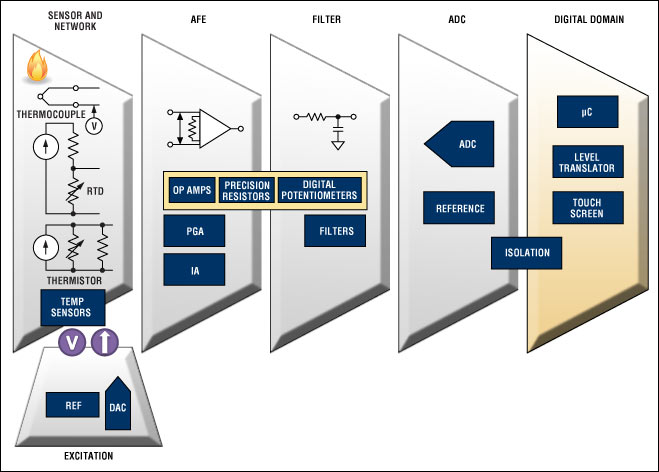
Block diagram of the signal chain in a temperature-sensing application. For a list of Maxim's recommended temperature-sensor solutions, please go t www.maxim-ic.com/-40+85.
Thermistors are temperature-dependent resistors, usually made from semiconducting materials like metal-oxide ceramics or polymers. The most widely used thermistors have a negative temperature coefficient of resistance and, therefore, are often referred to as NTCs. There are also positive temperature coefficient (PTC) thermistors.
Thermistor characteristics include a moderate temperature range generally up to +150°C, although some are capable of much higher temperatures; low-to-moderate cost depending on accuracy; and poor, but predictable linearity. Thermistors are available in probes, in surface-mount packages, with bare leads, and in a variety of specialized packages. Maxim also manufactures ICs like the MAX6682 and MAX6698 that convert thermistor resistance to a digital format.
A thermistor is often connected to one or more fixed-value resistors to create a voltage-divider. The output of the divider is typically digitized by an ADC. The thermistor's nonlinearity can be corrected either by a lookup table or by calculation.
Resistance temperature detectors (RTDs) are resistors whose resistance varies with temperature. Platinum is the most common, most accurate wire material; platinum RTDs are referred to as Pt-RTDs. Nickel, copper, and other metals can also be used to make RTDs.
RTD characteristics include a wide temperature range up to +750°C, excellent accuracy and repeatability, and reasonable linearity. For Pt-RTDs, the most common values for nominal resistance at 0°C are 100Ω and 1kΩ, although other values are available.
Signal conditioning for an RTD can be as simple as combining the RTD with a precision, fixed resistor to create a voltage-divider, or it can be more complex, especially for wide-range temperature measurements. A common approach consists of a precision current source, a voltage reference, and a high-resolution ADC, as shown in Figure 1. Linearization can be performed with a lookup table, calculation, or external linear circuits.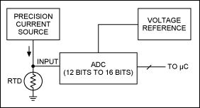
Figure 1. Simplified RTD signal-conditioning circuit.
Thermocouples are made by joining two wires of dissimilar metals. The point of contact between the wires generates a voltage that is approximately proportional to temperature. There are several thermocouple types which are designated by letters. The most popular is the K type.
Thermocouple characteristics include a wide temperature range up to +1800°C; low cost, depending on package; very-low-output voltage of about 40µV per °C for a K-type device; reasonable linearity; and moderately complex signal conditioning, i.e., cold-junction compensation and amplification.
Measuring temperature with a thermocouple is somewhat difficult because the thermocouple's output is low. Measurement is further complicated because additional thermocouples are created at the point where the thermocouple wires contact the copper wires (or traces) that connect to the signal-conditioning circuitry. This contact point is called the cold junction (see Figure 2). To accurately measure temperature with a thermocouple, a second temperature sensor must be added at the cold junction, as shown in Figure 3. Then the temperature measured at the cold junction is added to the value indicated by the measurement of the thermocouple voltage. The example circuit in Figure 3 shows one implementation, which includes a number of precision components.
Figure 2. Simple thermocouple circuit. The junction between metal 1 and metal 2 is the main thermocouple junction. Other thermocouples are present where the metal 1 and metal 2 wires join with the measuring device's copper wires or PC-board (PCB) traces.
In addition to all of the components shown in Figure 3, Maxim manufactures the MAX6674 and MAX6675 which perform the signal-conditioning functions for K-type thermocouples. These devices simplify the design task and significantly reduce the number of components required to amplify, cold-junction compensate, and digitize the thermocouple's output.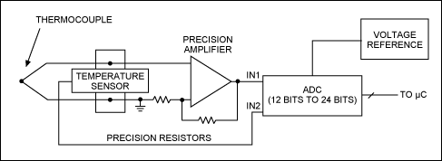
Figure 3. Example of a thermocouple signal-conditioning circuit.
Temperature-sensor ICs take advantage of the linear and predictable thermal characteristics of silicon PN junctions. Because they are active circuits built using conventional semiconductor processes, these ICs take a variety of forms. They include many features such as digital interfaces, ADC inputs, and fan-control functions that are not available in other technologies. The operating temperature range for temperature-sensor ICs extends as low as -55°C and as high as +125°C, with a few products operating to an upper limit of around +150°C. Descriptions of common types of temperature-sensor ICs follow.
Analog temperature-sensor ICs convert temperature to voltage or, in some cases, to current. The simplest voltage-output analog temperature sensors have just three active connections: ground, power-supply voltage input, and output. Other analog sensors with enhanced features have additional inputs or outputs, for example, comparator or voltage-reference outputs.
Analog temperature sensors use the thermal characteristics of bipolar transistors to develop an output voltage that is proportional to temperature. Gain and offset are applied to this voltage to provide a convenient relationship between the sensor's output voltage and the die temperature. Temperature accuracy can be excellent. The DS600, for example, is the industry's most accurate analog temperature sensor, with guaranteed error less than ±0.5°C from -20°C to +100°C.
Integrating an analog temperature sensor with an ADC is an obvious way to create a temperature sensor with a direct digital interface. Such a device is normally called a digital temperature sensor or a local digital temperature sensor. "Local" indicates that the sensor measures its own temperature. This operation contrasts with a remote sensor that measures the temperature of an external IC or a discrete transistor.
Basic digital temperature sensors simply measure temperature and allow the temperature data to be read by a number of interfaces including 1-Wire®, I²C, PWM, and 3-wire. More complex digital sensors offer other features, such as over-/undertemperature outputs, registers to set trip thresholds for these outputs, and EEPROM. Maxim manufactures several local digital temperature sensors, including the DS7505 and DS18B20 that guarantee accuracy of ±0.5°C over a wide temperature range.
A remote digital temperature sensor is also called a remote sensor or a thermal diode sensor. The remote sensor measures the temperature of an external transistor, either a discrete transistor or one that is integrated on the die of another IC, as shown in Figure 4. Microprocessors, field-programmable gate arrays (FPGAs), and ASICs often include one or more sensing transistors, usually called thermal diodes, similar to the one shown in Figure 4.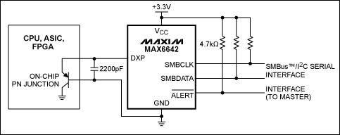
Figure 4. A remote temperature sensor, the MAX6642, monitors the temperature of a sensing transistor (or thermal diode) on the die of an external IC.
There is an important advantage to remote temperature sensors: they allow you to monitor more than one hot spot with a single IC. A basic single remote sensor like the MAX6642 in Figure 4 can monitor two temperatures: its own and an external temperature. The external location can be on the die of a target IC, as in Figure 4, or a hot spot on a board that it monitors with a discrete transistor. Some remote sensors monitor as many as seven external temperatures. Thus, eight locations, consisting of ICs and board hot spots, are monitored from a single chip. Consider the MAX6602 as an example. This temperature sensor has four remote diode inputs so it can monitor the temperatures of a pair of FPGAs with integrated thermal diodes, two board hot spots using discrete transistors, and the temperature of the board at the MAX6602's location. Both the MAX6602 and the MAX6642 mentioned here achieve ±1°C accuracy when reading external thermal diodes.
Current sensing is important in many applications and can be categorized into two popular approaches.
- In one approach current sensing is commonly used with higher currents and often in power-supply monitoring. Typical applications include short-circuit detection, transient detection, and reverse-battery detection.
- Current sensing is also used in applications that require much lower levels of current detection (down in the micro-amps), such as photodiodes that generate a small amount of current when exposed to light. Common applications are ambient light sensing, proximity detection, and light absorption-/reflection-based chemical process monitoring.
These current-sensing techniques employ current-sense amplifiers which are available in multiple configurations, or transimpedance amplifiers (TIAs). Each type of current-sensing amplifier is discussed below.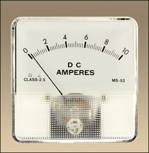
A variety of techniques are used to measure current, but by far the most popular is with a current-sense resistor. The basic principle of this approach is to amplify the voltage drop across the current-sense resistor by using an op-amp-based differential gain stage, and then to measure the resulting voltage. While discrete components can be used to build the amplifier circuit, integrated current-sense amplifiers have significant advantages over discrete implementations: better temperature drift, smaller PC-board (PCB) area, and the ability to handle wide common-mode ranges.
Most current-sensing applications employ either the low-side or the high-side principle. In the low-side technique the sense resistor connects in series with the ground path. The circuit deals with and the output voltage is ground referenced. However, the low-side sensing resistor adds undesirable extraneous resistance in the ground path. With the high-side principle, the sense resistor connects in series with the positive power-supply voltage. Here the load is grounded, but the high-side resistor must cope with relatively large commonmode signals.
Block diagram of the signal chain in a current-sensing application. For a list of Maxim's recommended current-sensing solutions, please go t www.maxim-ic.com/detect.
High-side current-sense amplifiers from Maxim employ a current-sensing resistor placed between the positive terminal of the power supply and the supply input of the monitored circuit. This arrangement avoids extraneous resistance in the ground plane, greatly simplifies the layout, and generally improves the overall circuit performance. The variety of unidirectional and bidirectional current-sense ICs from Maxim includes devices with and without internal sense resistors.
The second most popular current-measurement technique uses an op amp with very low input-bias current like a TIA, which converts the current input into a voltage output. This principle works for much smaller currents with large variations like those generated by photodiodes in light-sensing applications.
A simple photodiode is a very accurate transducer for sensing light. Light sensing is used in many different applications from power management based on sunlight, to sophisticated industrial process-control applications. Since illuminance in a given situation can vary over a broad range (e.g., from 20klx to 100klx), a wide dynamic range can be a key requirement for a light sensor. An integrated solution like the MAX9635, which integrates a photodiode, amplifier, and analog-to-digital converter (ADC), provides a dynamic range of 0.03lx to 130,000lx.
While proximity sensing can be done in many ways, using a photodiode provides higher accuracy and conserves more power than other methods. When the light hits the photodiode, a current is generated proportional to the strength of the light intensity. A buffer stage with low-input noise and high bandwidth transfers this current to the rest of the system. An amplifier with low input-current noise, such as MAX9945, provides accurate measurements.
A sensor communicates its sensed information with analog or digital techniques. Analog techniques are based on voltage or current loops. Digital information is communicated with CAN, CompoNet®, IO-Link®, RS-485, and other data interfaces.
Binary sensors only transmit single-bit information. Typically, the presence or absence of an object is detected and communicated with a logic level. Also, when an object like a piston in a valve reaches a predefined critical distance, the sensor detects and communicates this to the programmable-logic-controller (PLC) system through a binary interface.
Sensor interfaces have to be robust against all forms of mishandling and EMI, since the industrial environments are harsh.
1-Wire is a registered trademark of Maxim Integrated Products, Inc.
CompoNet is a registered trademark of OMRON Corporation.
IO-Link is a registered trademark of ifm electronic GmbH.
SMBus is a trademark of Intel Corp.
欢迎分享,转载请注明来源:内存溢出

 微信扫一扫
微信扫一扫
 支付宝扫一扫
评论列表(0条)