Add a Discrete Jack-Sensing Circuit to the MAX13330/MAX13331 AutomoTIve Headphone Amplifier
Abstract: This applicaTIon note describes how to add a discrete jack-sensing (JACKSENSE) circuit to the MAX13330/MAX13331 DirectDrive® headphone amplifier.
Attend this brief webcast by Maxim on TechOnline
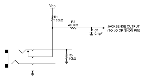
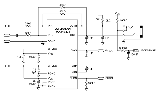
Jack-Sensing CircuitAdding a discrete jack-sensing circuit to a device typically requires just a few low-cost passive components. The exact values of each component depend on the system requirements, but the basic circuit should remain the same. Typically a four-contact audio jack is used where the extra contact is a normally-closed switch connected to the left or right audio contact. When a plug is inserted the switch opens. The circuit in Figure 1 shows the basic jack-sensing circuit. Figure 2 shows a schematic diagram of the MAX13330/MAX13331 with the jack-sensing circuit.
The jack-sensing circuit can be used to automatically enable the MAX13330/MAX13331 when a plug is inserted into the jack. Connect the output of the jack-sensing circuit directly to the active-low SHDN pin to implement this function.

Figure 1. Jack-sensing circuit.

Figure 2. Schematic diagram of MAX13331 with discrete jack-sensing circuit.
Filter SelectionThe RC filter consists of R2 and C1, and allows the jack-sensing detection times to be adjusted and the audio signals to be filtered. R2 and C1 can be selected to meet the requirements of each application. Table 1 gives a typical range of C1 capacitor values along with associated jack detection times and RC filter parameters.
If audio will be present when no plug is inserted into the jack and if the rising threshold of the digital input is < 2.2V, then select a capacitor value that will filter out the audio signal. The MAX13330/MAX13331 has a maximum audio signal of ~2.2V. Therefore, a capacitor value of 0.47µF is adequate to keep the jack-sensing output below 0.6V, which will be a "0" for most digital inputs. To minimize the jack detection times, adjust the capacitor value based on the specific digital input threshold.
A Schmitt-trigger inverter or buffer can be added to eliminate the need to filter the audio signal, as the rising-edge threshold will be above the maximum audio signal. With the small cost of the inverter/buffer, this modification provides the added flexibility of adjusting the jack detection times.
Table 1. Typical C1 Filter Values
**MAX13330/MAX13331 enabled (EN high) with no audio present.
欢迎分享,转载请注明来源:内存溢出

 微信扫一扫
微信扫一扫
 支付宝扫一扫
评论列表(0条)