OverviewThis applicaTIon note discusses the features of a reference design for Power-over-Ethernet (PoE) midspan or endspan inserTIon. The reference design's modular hardware allows flexible implementation of 4 to 192 Ethernet ports. The design is based on the MAX5945, a quad network power controller. A MAXQ2000 microcontroller provides system-level control, and controls and monitors the MAX5945 power controllers. The reference design can also be used in stand-alone mode, where it is configured by a PC over an RS-232 or USB interface.
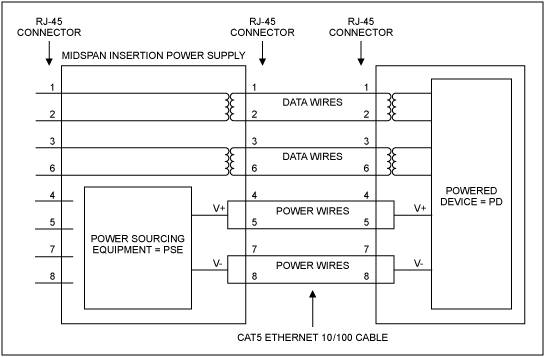
PoE OverviewFigure 1 shows the components of a PoE midspan insertion solution. For Ethernet 10/100, only two of the four available pairs of a CAT5 cable are used for data transmission. Therefore, the remaining two pairs can be used for power distribution. V+ is usually connected to wires 4 and 5, V- to wires 7 and 8. The midspan insertion power supply checks if a powered device (PD) is connected, ramps-up the supply, and monitors the current provided to the PD. In multiport solutions one can also assign priorities to the individual ports. This will ensure that the highest priority ports are always powered, while other ports can be switched off if the available power is insufficient.

Figure 1. Midspan insertion schematic for PoE.
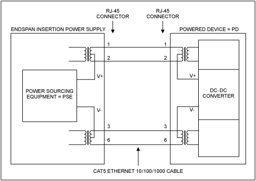
Figure 2 shows a typical schematic for a PoE endspan insertion solution. Data wires also carry the supply voltage. Here all four pairs of an Ethernet cable can carry data, so this solution is compatible with 1Gbps Ethernet.

Figure 2. PoE endspan insertion schematic.
Reference Design HardwareThe reference design hardware consists of:
- A motherboard and up to five DIMM 3.3V-format PC boards. The motherboard holds five 168-pin DIMM-style connectors, RJ-45 connectors/magnetics for 32 Ethernet-ports, a ±50V isolated RS-232 transceiver (MAX3250), and a SPI™-to-USB controller (MAX3420).
- Three types of DIMM-format cards.
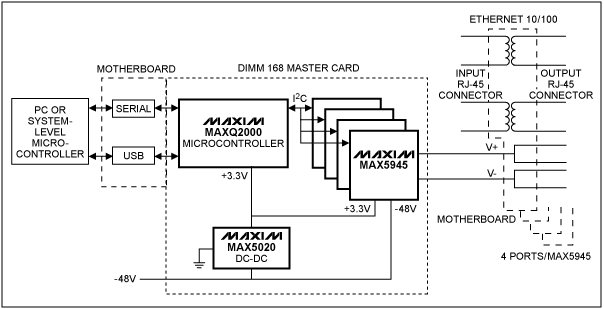
- A master card holds a MAXQ2000 microcontroller, a MAX5020 DC-DC converter to generate +3.3V output from -48V input, and six MAX5945 network power controllers to power 24 channels. The MAXQ2000 uses I²C to communicate with the MAX5945s, which are located either on the master card itself or on additional slave cards.
- A slave card holds six MAX5945 network power controllers to power 24 channels.
- A slave B card holds four MAX5945 network power controllers to power 16 channels

Figure 3. Block diagram of the reference design that features the MAX5945 PoE network controllers.
Reference Design FirmwareAs noted above, the reference design operates in either stand-alone mode or with a system-level microcontroller.
Operating with a system-level microcontroller, the system processor (supplied by the user) either configures any settings that would normally be set through I²C, or it simply lets the MAXQ2000 microcontroller use the built-in defaults. The reference design firmware allows the MAXQ2000 microcontroller to control up to 16 MAX5945 network power controllers on each of three I²C buses, for a total of 48 MAX5945 network power controllers. The system processor also specifies which events are to be reported, thus allowing the designer to exercise as much, or as little, control over the system as wanted. The MAXQ2000 retains settings in nonvolatile memory. A packet-based error-detecting protocol allows retransmission of packets, as needed, to ensure no loss of data.
When the design operates in stand-alone mode, the MAXQ2000 and associated firmware manage all the MAX5945s' operation. A PC sets parameters, which are saved in the microcontroller's nonvolatile memory. The PC can also query status and optionally retrieve a log of stored information. Communication between the PC and the MAXQ2000 is done through an RS-232 interface or USB.
From 1 to 48 MAX5945 quad controllers (thus providing 4 to 192 ports) can be connected to the MAXQ2000. The firmware supplied with the reference design will automatically detect and configure the appropriate number of ports, provided that each MAX5945 has an unique I²C address.
Reference Design DocumentationDocumentation for the reference design consists of:
- MAX5945_MAXQ2000_Design.doc file, a description of the reference hardware and firmware
- 32-Channel Schematic Motherboard Rev D.pdf, a schematic and layout of the motherboard
- MAX5945 24-Channel Ref Design Rev D.pdf, the schematic and layout of the 168 DIMM-format master and slave cards
- MAX5945_RefGuide.pdf, a User's Guide for the reference design
- MAX5945refspec.doc, a detailed description of the firmware and what it does
- MAX5945ver3_1.hex, the MAXQ2000 firmware
- MAX5945.exe, the PC software
SPI is a trademark of Motorola, Inc.
欢迎分享,转载请注明来源:内存溢出

 微信扫一扫
微信扫一扫
 支付宝扫一扫
评论列表(0条)