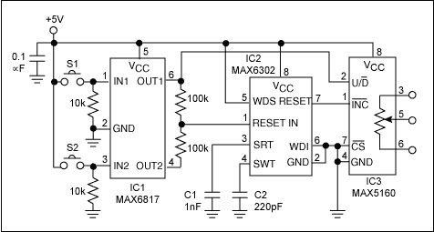
Digital potentiometer ICs such as the MAX5160 and MAX5161 are good replacements for mechanical types. But these ICs are designed to work with microcontrollers. In this manually operated digital potentiometer, two pushbuttons control the wiper resistance without a microcontroller (Figure 1).

Figure 1. This circuit provides manual up/down control of a digital potentiometer utilizing two pushbutton switches without using a microcontroller.
To mask the effect of contact bounce in mechanical switches S1 and S2, a dual switch debouncer (IC1) is used. A microprocessor-supervisor device configured as an oscillator (IC2) provides a clock signal to the digital potentiometer. Initially, OUT1, OUT2, and RESET are high. If S2 is momentarily depressed and released, OUT2 causes the RESET input of IC2 to go low. When S2 is released, OUT2 and RESET return high. A 5-bit resistive ladder internal to IC3 (similar to that of a 5-bit digital-to-analog converter) controls the wiper position. Therefore, this single cycle of oscillation lowers the wiper resistance by 1/32 of the total resistance range of the potentiometer.
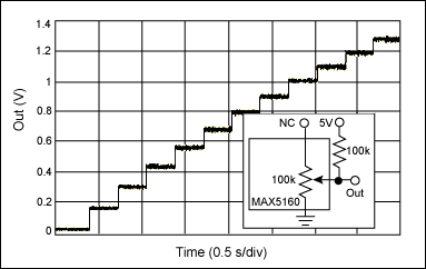
IC2 continues to oscillate if S2 is depressed and held. As a result, the resistance is lowered in a series of steps (Figure 2). Similarly, depressing S1 increases the potentiometer's resistance. Capacitors C1 and C2 set the frequency of oscillation at approximately 3Hz.

Figure 2. The resistance-ramp operation is observed by adding an external resistor to the wiper to form a voltage divider.
A similar version of this article appeared in the April 2, 2001 issue of Electronic Design.
欢迎分享,转载请注明来源:内存溢出

 微信扫一扫
微信扫一扫
 支付宝扫一扫
评论列表(0条)