Remote temperature monitoring traditionally has been accomplished with thermistors, thermocouples or temperature sensor ICs. If a system requires temperature measurements in multiple locations, the costs can quickly add up. The MAX1253/1254 and MAX1153/1154 provide a low-cost solution to monitor multiple remote temperatures as well as a single local temperature. In addition, these devices offer autonomous alarming functions without any interaction required by a host controller, generating an interrupt when a user programmable upper or lower threshold is exceeded, resulting in fully stand-alone temperature monitoring.
These IC devices monitor both arbitrary voltages and temperature, however this article will focus specifically on temperature monitoring and is therefore intended as a supplement to the MAX1253/54 and MAX1153/54 data sheet, which covers all the capabilities of the devices. Please see the device data sheet for alarming functions, device programming, specifications, etc. Basic Diode Temperature Measurements The forward voltage of a diode or diode-connected transistor (VBE) when operating at a constant current exhibits a negative temperature co-efficient of approximately 2mV/°C which can be used to measure the temperature at a remote diode. However, VBE can vary between diode manufacturers or even from device-to-device making absolute temperature measurements unpractical for volume production since calibration is required for each sensor. An alternate technique, which compensates for VBE variation uses measurements from two known currents to calculate temperature. This measurement depends on the ratio, rather than the absolute, and is inherently more accurate. The following equation is used in the MAX1253/1254 and MAX1153/1154.
Temperature = (VHIGH - VLOW) × q/(n × k × ln(IHIGH/ILOW) (°K)
Where:
VHIGH = sensor diode voltage with high current flowing (IHIGH)
VLOW = sensor diode voltage with low current flowing (ILOW)
q = charge of electron = 1.602. 10-19 Coulombs
k = Boltzman's constant = 1.38. 10-23 J/K
n = ideality factor = 1
To make temperature measurements using this method, the device performs two measurements using two separate constant current sources. The ratio between IHIGH and ILOW is trimmed at the factory. The device then calculates the temperature using the above equation and writes the result to the output register in °C.
Refer to Maxim application note: "Compensating for Ideality Factor and Series Resistance Differences between Thermal Sense Diodes", for additional information on the ideality factor. Using the MAX1253/1254 and MAX1153/54 The temperature measurement process in the MAX1253/MAX1254 and MAX1153/54 is fully automated. Switching of the current sources and VBE measurements are internally sequenced and require no user intervention. The resulting 12-bit (MAX1253/1254) and 10-bit (MAX1153/1153), 2's complement result represents the sensor temperature in degrees Celsius, with 1LSB = 0.125°C (12-bit) and 1LSB = 0.5°C (10-bit).
The MAX1253/MAX1254 and MAX1153/MAX1154 support both single?ended and differential temperature measurements or any combination of each. The design decision between the two types of measurement depends on the desired level of accuracy and on type or number of temperature sensors.

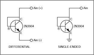
Figure 1. Connecting differential and single-ended temperature sensors.
Single-ended mode require a fewer number of connections per channel resulting in a simpler implementation with up to eight monitored temperatures for each IC device. Implementation is easy, just connect the anode of a diode-connected transistor to the input channel and the cathode to ground.
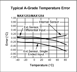
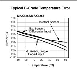
Differential-mode measurement allows for higher accuracy by providing common-mode rejection, but only allows four individual temperatures to be monitored for each IC device. Connect the anode of a diode-connected transistor to the even input channel and the cathode to the odd input channel of an input pair configured for differential temperature measurement. Figure 1 shows the diode connection. Please refer to Figures 2 and 3 for the typical temperature error for single-ended or a differential sensor.

Figure 2. Typical A-grade temperature error.

Figure 3. Typical B-grade temperature error. Sources of Error Due to the small signals associated with temperature measurements, proper layout techniques are important to minimize noise coupled into the analog inputs.
For single-ended measurements, choose ground connections for sensors away from high current return paths to avoid the introduction of errors caused by voltage drops in the board/system ground, the main drawback for single ended measurements. Practical options for better accuracy performance are the use of a star configured subsystem ground, or a signal ground plane. Isolate the anode sensor connection trace away from board and system noise sources; shield it with ground lines and ground planes (when available) to prevent accuracy degradation in the temperature measurements caused by magnetic/electric noise induction.
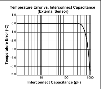
For differential measurements, run the two sensor connection lines parallel to each other with minimum spacing. This will improve temperature measurement accuracy by minimizing the differential noise between the two lines, since they will have equal exposure to most sources of noise. For further improved noise rejection, shield the two sensor connections by running them between ground planes, when available. You should minimize the capacitance between the AIN(+) and AIN(-) terminals as much as possible. Figure 4 shows the effect of this capacitance on the analog inputs when making a differential temperature measurement. One connection option is to use RG-6 cable, which has a capacitance of 50-75pF/M. This means that the device can tolerate up to 4 meters of this type of cable without significant impact to performance.

Figure 4. Effect of external sensor capacitance.
To help further reduce noise, the MAX1253/54 and MAX1153/54 have an on-chip averaging function that can be enabled. It can be programmed to average the result from 1 (no averaging) to 2048 times. The effect of averaging reduces the noise approximately by a factor of 1/sqrt(N). Selecting a Remote Temperature Sensor Temperature sensing accuracy depends on having a good-quality, diode-connected small-signal transistor as a sensor. Accuracy has been experimentally verified for 2N3904-type devices. The transistor must be a small-signal type with low base resistance. Tight specifications for forward current gain (+50 to +150, for example) indicate that the manufacturer has good process controls and that the devices have consistent VBE characteristics. CPU on-board sensors and other ICs' on-board temperature-sensing devices can also be used.
Table 1. Remote Sensor Transistor Manufacturers
欢迎分享,转载请注明来源:内存溢出

 微信扫一扫
微信扫一扫
 支付宝扫一扫
评论列表(0条)