IntroducTIonThis application note describes the register settings for Dallas Semiconductor's DS2148 and DS21348 (E1/T1/J1 line interface units) as a repeater for T1 or E1 operation. This can be accomplished with the device in either hardware or software mode.
The receive sensitivity for these two LIUs is programmable and is as much as -36dB for T1 applications and -43dB for E1 applications.
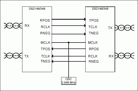
To simplify the design, it is recommended to use a 2.048MHz oscillator and use the internal register settings of the DS2148 and the DS21348 to convert the MCLK to 1.544MHz for T1 applications.

Figure 1. Typical T1/E1 repeater application.
The configuration settings of the DS2148 or the DS21348 in hardware mode are:
EGL = 0, ETS = 1 (long haul) EGL = 0, ETS = 0 (short haul)
EGL = 1, ETS = 0 (long haul)
RT1 = 1, RT0 = 1 (internal Rx side, 75Ω enabled)
The configuration settings of the DS2148 or the DS21348 in software mode are:
CCR1.6 = 0
CCR1.3 = 1
CCR1.1 = 1 CCR1 (00H) CCR1.7 = 0
CCR1.6 = 0
CCR1.3 = 1
CCR1.1 = 1
CCR2.2 = 1
CCR2.1 = 0
CCR2.0 = 0 CCR2 (01H) CCR2.3 = 1
CCR2.2 = 1
CCR2.1 = 0
CCR2.0 = 0
CCR4.1 (application dependent)
CCR4.0 = 0 CCR4 (03H) CCR4.7, CCR4.6, and CCR4.5 (application dependent)
CCR4.1 (application dependent)
CCR4.0 = 0
CCR5.1 = 1, CCR5.0 = 0
(internal Rx side, 100Ω enabled) CCR5 (04H) CCR5.5 = 0, CCR5.4 = 0
CCR5.1 = 0, CCR5.0 = 1
(internal RX side, 120Ω enabled)
CCR5.1 = 1, CCR5.0 = 1
(internal Rx side, 75Ω enabled)
欢迎分享,转载请注明来源:内存溢出

 微信扫一扫
微信扫一扫
 支付宝扫一扫
评论列表(0条)