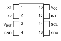
DS1678 Pin Assignment

DescriptionThis application note demonstrates how to use the DS1678 real-time event recorder which logs events—level transitions on the INT input pin—into a 1024-word datalog memory array. The first event is recorded as a time stamp; subsequent events are recorded as elapsed time from the previous event. The time stamp and 1024-word datalog memory accommodate up to 1025 recorded events.
This example code includes functions for initiating a datalogging "mission." The user-selectable options are event resolution, trigger selection, and rollover (handling missions of more than 1025 events). The software also includes routines for ending a mission, for displaying the event datalog information, and for writing and reading the user RAM.
OperationThe program uses two general-purpose port pins (GPIOs) on a microcontroller to communicate with the DS1678 through the DS1678's I²C serial interface. An additional port pin is used to toggle the DS1678's INT input to drive events. In a typical application, the INT input would be connected to circuitry that conditions the signals from the event source, e.g., a thermostat in a HVAC system. This connection allows the DS1678 to record, for example, the start time and duration of each cooling or heating cycle.
This example uses an 8051-compatible microcontroller, the DS2250. User inputs and data outputs from the program are passed through an RS-232 interface from a terminal emulator program on a PC to a UART on the microcontroller. The Microcontroller Tool Kit software utility can be used to program the DS2250 microcontroller.
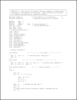
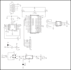
The software is shown in Figure 1. A schematic of the circuit is shown in Figure 2.

Download
Figure 1. Program listing for interfacing a microcontroller to the DS1678.

For Larger Image
Figure 2. Schematic for the DS1678 demonstration board.
欢迎分享,转载请注明来源:内存溢出

 微信扫一扫
微信扫一扫
 支付宝扫一扫
评论列表(0条)