In-Circuit Programming of the MAX16031/MAX16032 EEPROM-Based System Monitors
Abstract: The MAX16031/MAX16032 system monitors can be programmed after being soldered to the applicaTIon circuit board. This means that only unprogrammed devices need to be stocked, and that the latest version of the configuraTIon informaTIon can be written to the device during manufacturing test. A few simple measures, which are detailed in this applicaTIon note, ensure that the application circuit allows the programming hardware to share the I²C or JTAG bus line and provides power for the device during programming. The programming algorithm is also provided for both the I²C bus and the JTAG bus.
The MAX16031/MAX16032 EEPROM-based system managers are system supervisory devices that monitor eight power supply voltages, three temperature sensors, and one current. Each parameter is compared to four different thresholds, and several fault outputs can be configured to assert under a variety of conditions.
These monitors include an SMBus™-compatible I²C interface and a JTAG interface, both of which can access all of the device registers and program the internal configuration EEPROM. The MAX16031/MAX16032 are in-circuit programmable, as long as a few simple guidelines are followed.
The MAX16031/MAX16032 have a supply voltage range spanning 3V to 14V. Some applications connect VCC to a 12V intermediate bus voltage, while others connect VCC to a 3.3V auxiliary supply. It is possible to program these devices with a partially powered board. For example, the 3.3V auxiliary voltage could be applied without any other supplies, or the 12V intermediate bus voltage could be applied while all downstream power supplies are forced off to prevent power from reaching any other circuits. Another option is to use a commonly available dual diode to allow power to be supplied from the programming connector. Due to the voltage drop caused by the diode, this approach works best when the MAX16031/MAX16032 are powered from a 12V bus.
CC) and the pullup resistors are large enough, it can be possible to share the I²C bus for both programming and normal operation. If the µP's I²C bus lines are not open-drain, the ESD diodes will clamp the bus lines and interfere with programming. Sharing JTAG may require a JTAG bus multiplexer powered from 3.3V.
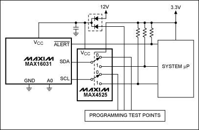
If the system µP does not have true open-drain I²C bus lines, a circuit like the one in Figure 1 can be used to automatically switch between the µP and the programming I²C bus.
Figure 1. The MAX16031 shares it's I²C bus through the MAX4525 multiplexer/switch.
The MAX4525 multiplexer in Figure 1 switches between the I²C connected to the system µP and the I²C connected to the programming test points. The switch is controlled by the VCC of the system µP. If VCC is not applied, but 12V is, the switch connects I²C to the programming test points. Once VCC is applied, the switch connects the I²C to the system µP. Note that, during programming mode, the programming hardware that connects to the test points must provide appropriate I²C pullup resistors.
The following figures show two different application circuits designed for in-circuit programming.
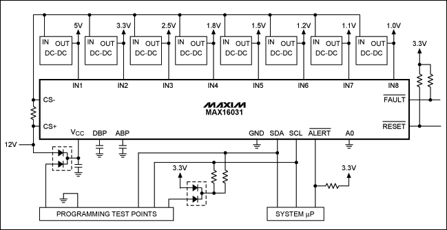
In Figure 2, the MAX16031 is powered from the 12V intermediate bus. A dual diode allows power to be provided by the programming connector, which also connects to the I²C lines of the MAX16031. These are shared with an onboard system-management µP with open-drain I²C outputs that do not load the bus, even when the µP is unpowered. As an alternative to an external programmer, the system-management µP can also program the MAX16031 on initial power-up. This also makes it easy to update the configuration of the MAX16031 without special hardware.
Figure 2. The MAX16031 is powered from a 12V intermediate bus and programmed in-circuit through the I²C bus.
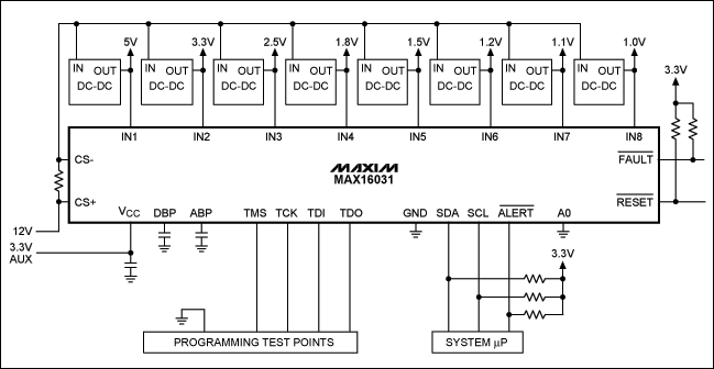
Figure 3 shows the MAX16031 being powered from a 3.3V auxiliary bus. Programming is accomplished through dedicated JTAG lines brought out to programming test points. For this example, the 3.3V auxiliary bus must be supplied before programming can be accomplished. The I²C interface still connects to a system-management µP.
Figure 3. The MAX16031 is powered from a 3.3V auxiliary bus and programmed through the JTAG port.
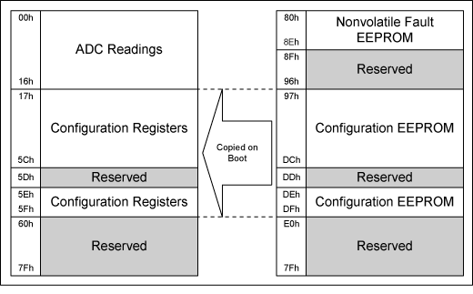
The MAX16031/MAX16032 have built-in EEPROM that stores the device configuration parameters. When power is applied, the contents of the EEPROM are transferred to the RAM registers. Both RAM and EEPROM are accessible from the JTAG and I²C interfaces. To correctly program the MAX16031/MAX16032, the desired parameters must be programmed to the EEPROM—see the memory map in Table 1.
Table 1. MAX16031/MAX16032 Memory Map
The MAX16031 evaluation kit (EV kit) software provides two types of configuration files. One is a human-readable text file produced by selecting System Save Configuration... This file can be used for I²C programming. The second is produced by selecting System Save as SVF... This file is in the serial vector format (SVF) used by many PLD vendors for JTAG programming.
The text file format is as follows:
[Registers]
register number=register value
.
.
.
All values are decimal. The registers begin at 23 and go to 98. These addresses correspond to RAM registers, not EEPROM addresses. To obtain the EEPROM address, add 128 to the RAM register address.
The SVF file format is described in more detail in the Serial Vector Format Specification (PDF, 85.2KB).
To program the MAX16031/MAX16032's EEPROM configuration memory, it is necessary to first make sure that the configuration-lock bit in register r5Fh[0] is zero. If it is not zero, write a '1' to that bit to clear it. To write to the EEPROM, load the starting address (97h) and follow it with a series of block-write commands (I²C) or write commands (JTAG). See the MAX16031/MAX16032 data sheet for details on the I²C protocols.
Pseudocode for a typical EEPROM programming process is as follows:
SendByte(5Fh)                 // Check lock bit
If ReadByte() & 1 == 1 Then
WriteByte(5Fh, 01h)           // Clear lock bit if needed
Loop Address from 97h to DFh
  SendByte(Address)           // Load address
  WriteBlock(Data, 10h)       // Write a block of 16 bytes
  Wait(16 * 11 milliseconds)  // Wait for programming
SendByte(Address)
ReadBlock(DataRead, 10h)      // Read back data block
If DataRead != Data Then
  RepeatCount = RepeatCount + 1
  If RepeatCount == 3 Then
    Fail
Else
  RepeatCount = 0
  Address = Address + 10h     // Advance to next block
Success
欢迎分享,转载请注明来源:内存溢出

 微信扫一扫
微信扫一扫
 支付宝扫一扫
评论列表(0条)