OverviewThis application note addresses the implementation of a DS2438-based Lithium-Ion battery pack with low-side n-channel safety FETs. A reference design is presented that focuses on Li+ cell safety and ESD-hardness. ESD protection components are recommended for applications where the DS2438 is connected directly across a cell and where protection FETs are present in the circuit and it is possible for device ground to be floating. Considerations on how the protection circuitry will affect the operation range and A/D accuracy of the DS2438 are also presented.
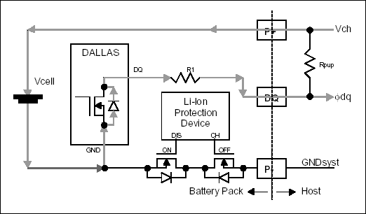
Li+ Safety ConsiderationsSafety will be considered first. Dallas recommends that no circuit should exist on the Li+ cell side of the safety FETs. Such a connection could compromise overall safety of the battery pack by potentially bypassing the safety FETs. An example of such a case is illustrated in Figure 1.

Figure 1. Potential charging path that bypasses safety FETs if Dallas chip is on the cell side.
The drain-to-body diode of the n-channel open-drain DQ output driver of the DS2438 could provide a charging path (highlighted in Figure 1) through the device that will bypass the protection FETs. This conduction path will exist only if the potential difference between VCH and ΦDQ is more than a diode drop greater than the sum of VCELL and the voltage drop across R1. While such a condition is unlikely, it does illustrate a possible way to bypass the safety circuit if the DS2438 is connected on the cell side of the safety FETs. Dallas thus recommends connecting the DS2438 on the terminal side of the safety FETs, unless otherwise recommended by the Li+ cell manufacturer.
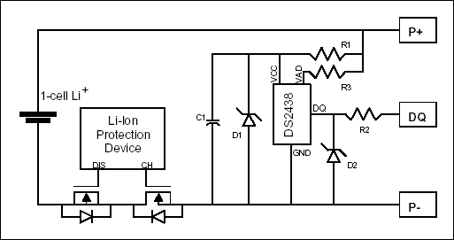
Dallas Reference DesignFigure 2 below illustrates the recommended implementation of the DS2438 with respect to the low-side n-channel safety FETs. Additionally, Dallas recommends passive devices that primarily serve to protect the DS2438 from ESD damage. The protection offered by each device is described below:

Figure 2. Recommended schematic for single-cell Li+ pack with low-side n-channel protection FETs.
- The capacitor C1 on VCC is simply a high-frequency bypass cap. 0.1 µF is recommended.
- The Zener diode D1 on VCC serves two purposes. It clamps at the Zener voltage so that ESD and switching transients cannot damage the Dallas chip through VCC. In the forward bias region, it clamps around 0.7 volts, thereby disallowing VCC from falling more than 0.7 volts below GND, which is possible when both the CHarge and DIScharge FETs are high impedance. Choose a Zener voltage that is larger than the maximum cell(s) voltage for the application, but lower than the 10.0 volts rating of the DS2438. A Zener value between 5.1 volts and 10.0 volts would be ideal for the circuit in Figure 2.
- The resistor R1 in series with VCC limits current through the device and the protection Zener D1. A minimum R1 value of 510Ω is recommended to protect during conditions when ground is floating (CHarge and DIScharge disabled). If the circuit does not have charge protection and GND will never be in a floating state, an R1 value of at least 330Ω is recommended. Since the maximum active current of the DS2438 is 100 µA, this represents a 50 mV drop worst case.
- The Zener diode D2 performs the same function for DQ as D1 does for VCC. Choose a Zener value larger than the communication logic high level for the application, but lower than the 5.5 volts maximum rating for DQ. If the application does not allow for a floating ground condition, this component is not required.
- The resistor R3 in series with VAD limits current through another possible ESD path from VCC. A value of at least 510Ω for R3 is recommended. Please take into consideration the possible voltage drop and resulting A/D inaccuracy when selecting an R3 value.
欢迎分享,转载请注明来源:内存溢出

 微信扫一扫
微信扫一扫
 支付宝扫一扫
评论列表(0条)