The MAX1460 has lots of talent, but its processor will never be a star. Why? Because it doesn't aspire to be. That's the innovative twist: A Smart ADC with integrated processor, designed for sensor applications. The smart, but quiet, processor compensates for sensor errors. This application note describes how.
As in a movie, the big star chips (like micros and memories) garner all the attention and adulation. But although they're given little more than a few seconds of scrolling fine print in the credits, others are just as important when it comes to getting the film in the can.
The headliners rely on a supporting cast of chips to handle glue logic and real-world interfacing. Regulators, voltage comparators, op-amps, filters, analog converters, and communications transceivers all have roles to play. In the quest to cram everything on a single chip, the next step is to integrate these nondigital support functions onto the MCU, creating what's best described as a mixed-signal micro.
It's not hard to imagine other mixed-signal leaders making a move. So, I was excited, but not surprised, when I heard Maxim was working on a processor. For those (presumably few) of you not familiar with the company, Maxim has done well by offering a huge selection of mixed-signal problem solvers including ADCs, DACs, op-amps, supervisors, transceivers, and the like.
This being their first showing in the processing theatre, the MAX1460 (Photo 1) is best described as a smart ADC because the on-chip 16-bit processor isn't user programmable. The processor isn't the star; it plays a supporting role.
Photo 1. They call it a smart ADC, and the MAX1460 arguably represents Maxim's first entry into the micro market.
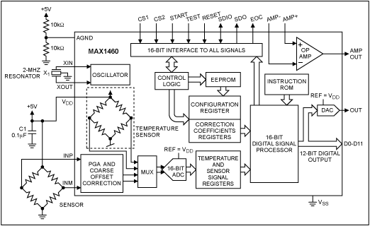
Figure 1 gives you a backstage look. The on-chip processor is one link in a signal chain that includes a programmable gain amp, 16-bit ADC, temperature sensor, 12-bit DAC, and op-amp.

Figure 1. The MAX1460 combines everything needed to accommodate a variety of bridge-type sensors. Major integrated functions include a programmable gain amp (PGA), 16-bit ADC, temp sensor, and 16-bit processor.
The micro is described as a RISC or DSP, presumably combining aspects of both (not that there's much difference anymore). At this point, the details of the architecture and on-chip ROM code haven't been disclosed, although much can be inferred by the functions they perform. Piezo De ResistanceTo get a better idea of what the MAX1460 is, let's look at where it came from and what it's supposed to do. The MAX1460 is designed to act as a signal-conditioning front end for a variety of sensors, especially those based on the classic Wheatstone bridge.
The Wheatstone-bridge concept exploits the fact that physical energy (tension or compression) causes a change in resistance detected as a voltage differential between the two legs of the bridge. The Wheatstone bridge is versatile. Use gravity as the physical input and you've got a scale. Turn it sideways and it's an accelerometer. Mechanically connect it, and voilà, a strain gauge. Use the bridge as a diaphragm and it detects pressure, level, and flow.
That's the good news. The bad news is extremely low-level output that is hard to detect and easily swamped by ambient electrical interference. A typical piezo-resistive bridge sensor may be able to generate only 20mV or so per volt of excitation. In a 5V system, that means the peak output is 100mV, which even at meager 8-bit resolution requires the ability to detect low-level signals down to hundreds of microvolts per least-significant bit. Push for 12-bits and you're talking nanovolts!
Resistors also react to temperature (i.e., thermistor), which is nice when that's what you want to do. Otherwise, it's a pain. An uncompensated sensor may exhibit thermal errors on the order of 10, 20, or even 30% of full-scale output (FSO) including significant (e.g., 5% FSO) nonlinearity. Without temperature compensation, there's no need to worry about A/Dresolution because even a few bits of accuracy will be tough to obtain. You know the drill. Get some op-amps, a temp sensor (to compensate), ADC, MCU, and a grab bag of discretes, then have at it. Amplify the input and remove any offset, compensate (both gain and offset) for temperature, and output the digital result.
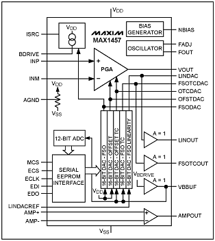
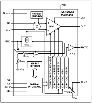
Earlier parts like the MAX1457 and '58 (see Figure 2), put together a few parts of the puzzle. The main difference is that the '57 uses a relatively large (128 ' 16) external EEPROM to store temperature compensation coefficients and the '58 has a smaller EEPROM (8 ' 16) on chip.

Figure 2a.

Figure 2b.
Figure 2. Earlier Maxim parts, the MAX1457 (a) and MAX1458 (b), targeted the same bridge sensor applications but required support from an external ADC and micro.
The different size of the EEPROM reflects a fundamental difference in the '57's and '58's approach to compensation. It starts by realizing that the goal of compensation is to come up with curves that cancel the sensor's output and offset thermal error curves. Every programmer knows there are two ways to generate a curve. Either come up with an equation that defines the curve, or use a table lookup. That's the difference between the '57 and '58.
The '57 relies on its larger EEPROM to store a table of output and offset compensations corresponding with up to 120 temperature points. This setup enables the output to be fine-tuned across the entire temperature range, yielding excellent 0.1% accuracy. Meanwhile, the '58 (essentially an analog computer hardwired to execute one calculation) uses an equation incorporating error coefficients. An equation of only a few terms takes up a lot less room in memory than a table, hence the '58's smaller EEPROM. But, a simple equation usually does not perfectly fit a real-world curve, so the '58's accuracy (1%) isn't as good as the '57's. Still, 1% is good compared to the 10-20% or greater error of an uncompensated sensor.
Although a big improvement over rolling your own, the '57 and '58 are still analog from the system designer's point of view. Not only do you have to come up with an ADC and the software to babysit it, you're likely to encounter problems getting the analog signal from here to there, especially in a high-temperature or otherwise harsh environments where the sensor and controller are physically separated.
Little Signal, Bit BitsEnter the MAX1460. By adding the ADC and micro, the '1460 puts everything under one roof, inputting a tiny signal from the bridge and outputting accurate (0.1%, 12-bit) 1s and 0s. The operating principle is exactly the same as before, but now most of the details and sensitive analog signals are handled on chip.
The design is ratiometric (i.e., relative to supply voltage) with input centered around a virtual ground, obtained by connecting 10kW pull-up and pull-down resistors to AGND. Maxim recommends avoiding the extremes of the input range for best signal-to-noise ratio (SNR). So, it's best to try to keep the input between 1 and 4V rather than the full-scale 0-5V.
The first step is coarse amplification ('46, '61, '77, or '93) and offset correction (eight selections) to get dynamic range into the ballpark. The output is a differential voltage between -VDD and +VDD that, post-A/D conversion, is interpreted as an integer value between -32768 and +32767 or, for correction coefficients, a fraction between -1.0 and +0.99997. Once digitized by the 16-bit ADC, the coarse-adjusted input and on-chip temperature-sensor reading are fed to the processor. Although the output is only 12-bits, 16-bits of resolution are required here to prevent quantization and rounding errors from polluting the final output.
The other set of processor inputs comes from the correction-coefficient registers in Table 1 that reflect the offset and output specs for a particular sensor, including thermal characteristics.
Table 1. The key calculation performed by the on-chip processor compensates sensor offset and gain temperature by using sensor-dependent correction coefficients.
欢迎分享,转载请注明来源:内存溢出
赞
(0)
打赏
 微信扫一扫
微信扫一扫
 支付宝扫一扫
 微信扫一扫
微信扫一扫
 支付宝扫一扫
监控摄像机基础配件你都清楚吗
上一篇
2022-08-05
商场对视频监控存在怎样的需求
下一篇
2022-08-05

评论列表(0条)