
Intersymbol interference places the main limitaTIon on the maximum allowable distance for RS-485 communicaTIons, but pre-emphasis is extremely effecTIve in reducing this interference.
Signal-transmission systems contend with two major obstacles: losses that reduce the signal amplitude and energy storage that alters the signal's shape. A signal-transmission system is the electrical channel between an information source and its destination (Figure 1). You can define pre-emphasis as any change that you make at the source, before the electrical channel, that improves signal quality at the destination. Whatever else you call pre-emphasis (precompensation, pre-equalization, predistortion, or accentuation), the technique reduces noise and distortion by increasing the magnitude of some frequency components. To restore the signal and improve the SNR, a system usually follows pre-emphasis by its converse: de-emphasis.
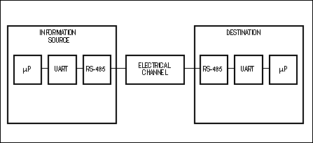
Figure 1. A signal-transmission system includes the electrical channel between the information source and its destination.
Many applications use pre-emphasis techniques. In IC-layout programs, for instance, pre-emphasis adjusts the line widths to compensate for etch-rate variations that occur around corners. In disk-drive controllers, pre-emphasis compensates for poor frequency response near the center of the disk. Another type of pre-emphasis, Dolby B, reduces tape hiss by boosting low-level signals in the middle- and high-frequency audio bands when recording and then reversing this process during playback. In the latter two cases, qualities inherent in the media between the source and the destination accomplish the de-emphasis.
Distance versus Data RateYou can also apply pre-emphasis techniques to RS-485 communications. Most RS-485 users want to know the answer to one crucial question: How far can you reliably transmit and receive data at a specified data rate? RS-485 transceivers operate across 4000ft and at 10Mbps, but not at the same time. The trade-off has always been less distance at a higher rate or greater distance at a lower rate.
Pre-emphasis does not allow you to run 10Mbps across 4000ft, but it considerably improves the situation (Figure 2). RS-485 transceivers without driver pre-emphasis or receiver equalization generally acquire 10% jitter across 1700ft at a fixed data rate of 1Mbps. At that data rate, adding driver pre-emphasis allows you to double the distance to 3400ft without increasing the jitter. Alternatively, pre-emphasis can increase the data rate for a fixed-cable distance. Non-pre-emphasis parts operating at 400kbps generally acquire 10% jitter over 4000ft. Adding pre-emphasis enables you to transmit as much as 800kbps for this distance.
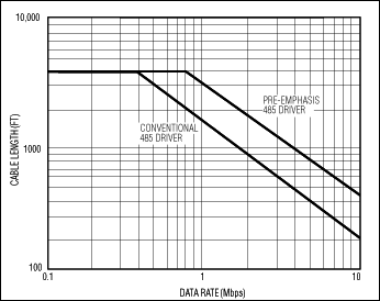
Figure 2. At 10% jitter, pre-emphasis enables a greater transmission distance.
IR Losses and Jitter Impose LimitsThe two major effects that limit the maximum length for a given type of transmission line in RS-485 communications are current-times-resistance (IR) losses and signal jitter. Transmission-line resistance is usually negligible in comparison with termination resistance at the end of the line. However, when transmission lines are greater than 4000ft, you can't ignore the line resistance. IR losses result from the resistor divider, which consists of the cable resistance and the termination resistor. These losses diminish the signal magnitude by -6dB at 4000ft (down 50%) for a PVC-insulated, #24 AWG twisted-pair cable with a characteristic impedance of 100V.
Signal jitter is primarily due to intersymbol interference (ISI). ISI is the net effect of several causes of signal degradation. One cause is the attenuation and the dispersal of frequency components that result from signal propagation down a transmission line. Another cause is the variation of rise and fall times that follow the varying sequences of ones and zeros known as "pattern-dependent skew." A data pulse responds to these effects with a loss of amplitude, displacement in time, rounded edges, and a "smearing" of the pulse into adjacent time slots, or unit intervals.
For a fixed amount of jitter (10% in Figure 2), the cable-length-versus-data-rate curves exhibit a "breakpoint" that represents the cable's bandwidth at the receiving end after 4000ft. This breakpoint occurs at data-rate values that depend on the shape and the slew rate of the signal at the transmitting end. Because of the cascaded lumped-element network of the cable, the rolling-off slopes are identical.
Thus, one way to extend distance for a given data rate is by reducing the effect of jitter that ISI causes. Figure 2 shows such a reduction; pre-emphasis pushes the curve to the right, enhancing reliable communications by increasing the allowable maximums for data rate and transmission distance.
To fully understand how pre-emphasis works, analyze the technique in both the time and the frequency domains. First, consider ISI and pre-emphasis in the time domain.
A UART determines when to sample a received data stream by looking for the first transition from one to zero. The UART then waits for one half of a unit, or bit interval (tb /2), to see whether the signal is still zero. ISI is problematic for a UART, because the difference, or spread, in transition times can eventually increase the bit-error rate. Figure 3 shows the ISI, or pattern-dependent time skew, that results from three bit patterns. ISI is also a substantial problem for UARTs, because data reliability decreases sharply when the total jitter on an RS-485 signal becomes 10% or more of the baud period. The cable's RC time constant, which limits the bandwidth, causes part of the jitter to depend on bit patterns in the data. This pattern-dependent ISI accounts for a majority of the jitter in an RS-485 system.
Figure 3. Intersymbol interference depends on bit patterns in the data, such as a 1111 0000 pattern (top trace), a 0011 0011 pattern (middle trace), and a 0001 0111 pattern (bottom trace).
A series of ones followed by a zero, for instance, causes the transmission-line voltage at the end of the string of ones to rise to the highest-possible level, such as the level of signal 1 in Figure 4. A signal at this high level takes the longest time to reach the zero crossing. On the other hand, if the data pattern consists of a string of zeros followed by a one and then a zero, the one-to-zero transition (signal 2 in Figure 4) starts from a voltage much closer to the zero crossing. Therefore, signal 2 takes less time to reach the zero crossing. A signal's propagation delay depends on its preceding bit pattern; this pattern-dependent skew is ISI.
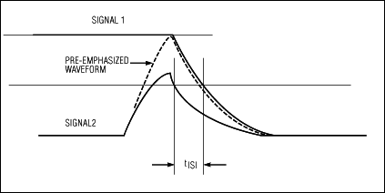
Figure 4. Adding amplitude for a specified amount of time to the waveform that results from a 0000 0010 bit pattern (signal 2) produces a pre-emphasized waveform (dotted line) that minimizes intersymbol-interference time skew (tISI) with respect to the waveform that results from a 1111 1110 bit pattern (signal 1).
Four Voltage LevelsA pre-emphasis driver that incorporates four voltage levels (strong high, strong low, normal high, and normal low) counteracts this effect (see Appendix A, RS-485 Transceivers Implement Pre-Emphasis). Pre-emphasis is necessary only when the data pattern changes and not during the intervals when the signal voltage remains at the same logic level. On the other hand, the need for pre-emphasis is constant for signals with logic-level changes at every bit interval.
If the driver input changes from logic low to logic high, the differential output voltage switches to a strong high. This action eliminates time skew by forcing the signal to a high-voltage level comparable with the voltage level following a constant string of ones. A typical waveform, such as the dotted line in Figure 4, demonstrates how pre-emphasis reduces skew by boosting the amplitude of signal 2 to that of signal 1. This strong-high level, which is typically 1.9 times' larger than the normal-high level, minimizes ISI by counteracting the signal-voltage attenuation that results when a data pattern constantly changes its logic state.
The typical differential pre-emphasis waveform changes with bit patterns at the driver input (Figure 5). For instance, if the driver input switches from logic low to logic high, the differential pre-emphasis waveform goes to the strong-high voltage level. The strong-high level returns to normal high at the end of the pre-emphasis interval, which in this case is 100nsec. If the driver input switches back to a logic low before the end of a pre-emphasis interval, the differential output switches directly from strong high to strong low. Similar but opposite output transitions occur in response to a high-to-low driver-input transition.
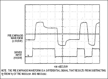
Figure 5. The output of a differential pre-emphasis driver varies with logic changes at the driver input.
To quickly evaluate your circuit configuration, view an eye diagram (see Appendix B, Eye Diagrams Provide Quick Answers). Eye diagrams let you measure the total time variation, or jitter, at the differential 0V crossing, which you can then express as a percentage of one bit interval, tb : % jitter = (total jitter/tb)3100. Limiting this percentage to 10% generally ensures error-free operation. Typical eye diagrams illustrate the improvement in signal quality when using a pre-emphasis driver instead of a non-pre-emphasis device under the same conditions (Figure 6).
Figure 6. Eye diagrams based on 5Mbps data over 1000 feet show the advantage of using a pre-emphasis driver (a) the MAX3292 in this case over a non-pre-emphasis industry-standard 75180 (b).
Pre-Emphasis in the Frequency DomainTo analyze how pre-emphasis works in the frequency domain, consider the typical model of an infinite transmission cable, which consists of an infinite number of cascaded lumped-element LRCG networks (Figure 7). The R and C components cause most of the major effects in RS-485 applications, as you can easily see when viewing the differential response at the receiver input following a long cable. The cable response resembles the response of an RC low-pass filter (Figure 8). For practical purposes and ease of discussion, you can assume that the transmission cable acts as a simple RC low-pass filter.
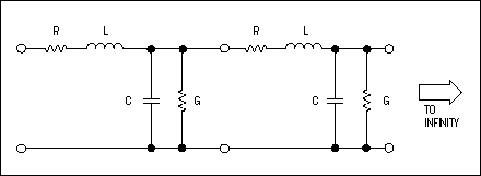
Figure 7. A standard model for a transmission line comprises an infinite number of cascaded LRCG networks.
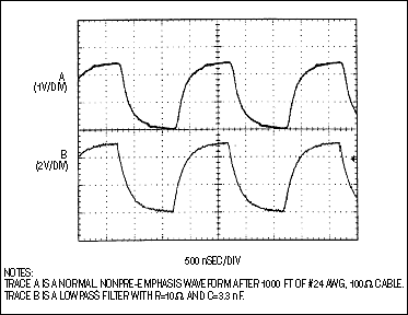
Figure 8. The step response following 1000 feet of cable (trace A) is similar to that of a simple RC low-pass filter (trace B).
Pre-emphasis adds high-frequency components to counteract high-frequency attenuation by the transmission cable. RS-485 transmitters currently transmit at two voltage levels (high and low), producing square waves with 50% duty cycle that contain only odd harmonics of the fundamental frequency (Figure 9a). A square wave with non-50% duty cycle (25%, for instance) produces both even and odd harmonics of the fundamental frequency (Figure 9b).
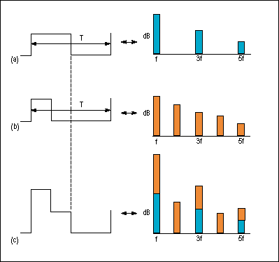
Figure 9. Adding the odd-harmonic spectrum of a 50%-duty-cycle square wave (a) to the even-odd spectrum of a 25%-duty-cycle square wave (b) forms one of the many spectra possible for a pre-emphasis waveform (c).
In contrast, transmitters with pre-emphasis, such as the MAX3291/MAX3292, generate four voltage levels, as in Figure 5. For a specified pre-emphasis interval, the extra levels boost the amplitude at every transition edge, producing an additional pulse in amplitude that contains both odd and even harmonics of the fundamental frequency. These odd and even harmonics of the pre-emphasis pulse add to the frequency spectrum of the original square wave, thereby reducing ISI by counteracting the low-pass-filter response of the cable (Figure 9c). This figure demonstrates the pre-emphasis-high, normal-high, and normal-low voltage levels but omits the pre-emphasis-low level for clarity.
Appendix A RS-485 Transceivers Implement Pre-EmphasisEngineers at Maxim found that intersymbol interference places the main limit on the maximum distance for RS-485 communications and that pre-emphasis is extremely effective in reducing this interference. Based on this finding, these engineers developed two RS-485 transceivers that incorporate internal pre-emphasis (Figure A). Each transceiver includes a timer for generating the pre-emphasis interval (Figure B).
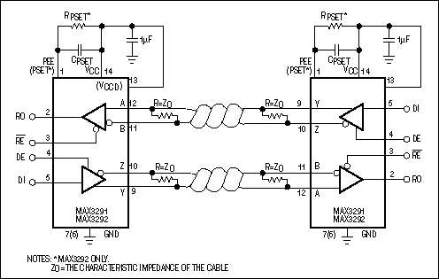
Figure A. RS-485 pre-emphasis transceivers easily fit into 75180 sockets.
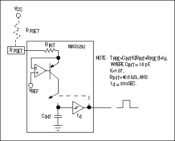
Figure B. Internal pre-emphasis timers provide for fixed or adjustable pre-emphasis intervals.
The MAX3291 is pin-compatible with the industry-standard 75180 and has a fixed pre-emphasis interval that optimizes it for data rates from 5Mbps to 10Mbps. The MAX3292 has a variable pre-emphasis interval, set by an external resistor between VCC and PSET, that allows data rates to 10Mbps. This resistor and its corresponding capacitor are the only modifications necessary to operate the MAX3292 in a 75180 socket. The proximity of VCC and PSET (pins 1 and 14) lets you implement the change with minimal effect on the circuit layout.
Appendix B Eye Diagrams Provide Quick AnswersAs a tool for designers of digital transmission lines, the eye diagram provides quick answers to the following basic questions without the need for a complex mathematical analysis: What is the maximum allowed line length and data rate for my proposed system and how much transition jitter will it exhibit?
An eye diagram is simply an oscilloscope display of random digital data on the line, triggered on every nth cycle of the associated clock signal. The resulting superposition of waveforms, which should include every bit sequence possible within the n-cycle window, produces an eyelike opening that repeats for each unit interval (Figure 6).
For a given pulse code, such as NRZ, an eye diagram lets you determine the condition, such as intersymbol interference = 10%, that significantly degrades the system timing and amplitude margins and for which the bit-error rate (BER) increases sharply. An increase in the BER also depends on the type of UART in the system.
The eye diagram also reveals other useful information, based on the following facts:
- tolerance for timing and amplitude variations is proportional to the size of the eye,
- channel-noise margin is proportional to the height of the eye,
- allowed timing errors are proportional to the width of the eye, and
- jitter, BER, and the difficulty of recovering a clock signal from the asynchronous data stream are all proportional to the width of the transition region.
A similar version of this article appeared in the June 10, 1999 issue of EDN.
欢迎分享,转载请注明来源:内存溢出

 微信扫一扫
微信扫一扫
 支付宝扫一扫
评论列表(0条)