Conference: IEEE InternaTIonal Solid-State Circuits Conference 1999
Session: CommunicaTIons
Author: Michael J. McCullagh
AffiliaTIon: Symmetricom Ltd
Contact details:
Michael J. McCullagh
Principal Design Engineer,
Symmetricom Ltd
Mansard Close
Westgate
Northampton
NN5 5DL
England
Tel +44 (0)1604 586744
Fax +44 (0)1604 585599
An RF/IF silicon bipolar ASIC, ROCIII (receiver-on-a-chip) has been designed to deliver a receiver soluTIon for a range of GPS/GLONASS products aimed at the professional marketplace. These applications include synchronisation of cellular base stations (high blocking immunity) and survey grade receivers with sub-cm accuracy (low amplitude and phase noise). The ROCIII delivered successful performance after a single design pass and has now gone into production. The ASIC is packaged in chip-on-board (COB) modules that also contain the extra passive components and control loops. Each COB module is targeted at a specific set of applications and has the advantage of being a rugged component that can be directly placed on a digital motherboard using standard, surface mount, manufacturing techniques.
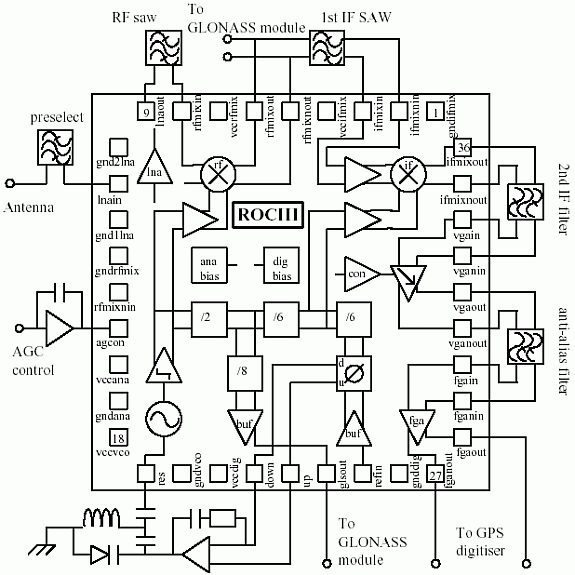
A simplified schematic of the ROCIII, embedded in a GPS/GLONASS COB module is contained in Figure 1. The 1.91mm x 1.71mm ASIC was designed on the Maxim GST-2 silicon bipolar process with a headline Ft of 27GHz. It operates from a supply voltage of 2.7V to 3.3V and draws a DC current of 53mA. The operating temperature range is -40° to +85°C. Gain, noise figure and input referred IP3 (IIP3) information for each stage and the complete receiver is contained in Table 1. The receiver employs a dual down-conversion scheme that offers good frequency selectivity and high attenuation of image responses that could compromise out-of-band jamming performance. Another advantage is the extra stability margin that is afforded via gain distribution between RF, 1st IF and 2nd IF frequencies, especially given that the total on-chip operating gain for nominal AGC conditions is 130dB. 1st LO radiation is also low which is important for multiple receiver systems.

Figure 1. Simplified schematic of ROCIII embedded in a GPS/GLONASS COB module.
Table 1. Gain, noise figure and IP3 for ROCIII circuits and complete receiver.
Lossy match on input
Effective IP3 cut-off point
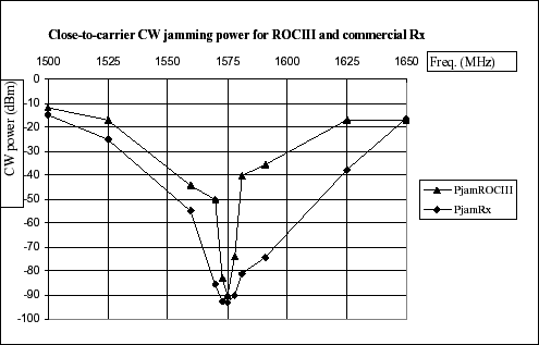
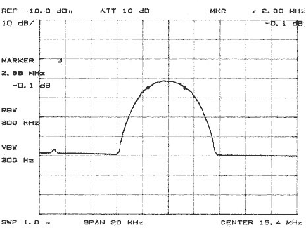
A key feature of the receiver is that it combines good linearity with a high level of RF gain that allows for a high selectivity, but high insertion loss, SAW device as the 1st IF filter. This filter delivers a high degree of close to carrier jamming margin as well as acting as an effective 3rd order intermod. product cut-off point. Figure 2 contains a plot of jamming powers close to carrier for a ROCIII COB module compared to a GPS receiver that has been designed specifically for C/A-code military applications. The improvement of up to 40dB is very significant. Both receivers give similar blocking performance at the main cellular transmit bands of 940 and 1840MHz. Note that the in-band jamming power is limited by the carrier tracking loop bandwidth in the DSP. The frequency response of the GPS strip of the receiver is contained in Figure 3 and was obtained by sweeping the RF input frequency from 1570.42MHz to 1580.42MHz and recording the GPS 2nd IF output.

Figure 2. Comparison of close-to carrier jamming powers for ROCIII module and commercial receiver.

Figure 3. Swept frequency response of receiver's GPS strip, relative scale on Y-axis.
The frequency plan captured in the ROCIII operates from a low cost reference of 20MHz and has RF=1575.42MHz, 1st IF=135.42MHz, 2nd IF=15.42MHz. A separate output at 90MHz is provided from the ROCIII synthesiser that acts as a reference for an external, low cost GLONASS IF module. This module is based around two commercial ICs, a VHF downconverter and a dual modulus prescaler. Extra division within this module (f/160) provides a PLL comparison frequency of 0.5625MHz that exactly equals the GLONASS channel spacing and hence allows the unit to select the various GLONASS satellites. The VHF downconverter is driven via an IF filter by the ROCIII RF mixer outputs.
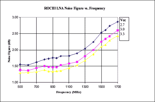
The LNA uses a 2 stage shunt/series feedback topology and does not require external matching. The DC supply is delivered via a l/4 stripline connected to the output port and the circuit is self-biasing. A plot of noise figure over the band of interest and at three Vcc levels is contained in Figure 4. The measured performance detailed in Table 1 compares well with the simulation results obtained from Maxim's SPICE based Analog Design System (ADS) which are Gain=18.5dB, NF=2.4dB and IIP3=-13.9dBm.

Figure 4. Noise figure over frequency for ROCIII LNA at three Vcc values.
The RF downconverter is based on a double balanced Gilbert cell with LO drive provided from a low impedance differential pair. Both the Gilbert cell and LO drive are PTAT biased via a classical arrangement. Bias current for both stages is optimised to minimise noise figure, maximise IP3 and maximise gain. The RF input is matched externally via a lossy match technique. The typical source for this circuit is a single-ended, 50Ω RF SAW used as an image reject filter. The IF output is delivered via low output impedance emitter followers and is suitable for driving directly the 135MHz IF SAW. The deliberate mismatch keeps the group delay distortion of the SAW within an acceptable level by attenuation of the triple-transit response. One aspect of circuit performance not covered in Table 1 is LO power at mixer RF input = -49dBm (equivalent to 40dB LO to RF isolation).
The IF down-converter has a preamplifier plus Gilbert cell type topology with PTAT biasing. The circuit has been optimised to deliver a high level of conversion gain with good noise figure. A differential input termination resistor (off-chip) of 100Ω is used to minimise SAW group delay distortion. The moderate IIP3 value of -28dBm for this circuit is more than adequate given the relatively narrow bandwidth of the preceding 1st IF SAW (2.8MHz).
The variable gain amplifier compensates for total receiver gain variation to ensure that the noise signal delivered to the 3-level digitiser is always at the correct level for optimum coding. In conjunction with the DSP, the VGA also implements an adaptive digitisation threshold scheme that helps to mitigate against in-band jamming signals. The circuit has a useful gain control range of greater than 60dB, with a maximum gain level of 18dB. Both the absolute gain level, gain range and gain slope have been compensated for temperature and supply variations. The gain control input is processed by a control signal compensation amplifier before being applied to the VGA current steering core. This compensation amplifier is based around a multi-tanh doublet input stage that provides a very linear gain slope. The fixed gain amplifier circuit provides 40dB of differential, DC coupled gain and can deliver close to 1V of single ended swing before entering compression. It is designed to drive either a separate digitiser or a companion digital ASIC (under design). In order to ensure that the total swing is available over the complete temperature range, the final output stage is biased from a source that delivers constant current with temperature rather than PTAT.
The core of the L-band VCO is based on a common collector Clapp topology with square root PTAT biasing and signal extraction from the base node. This circuit has been optimised for low noise, high signal swing without asymmetrical clipping and maximum resonator loaded Q. The signal is fed to two limiting amplifier structures that are designed to deliver constant signal swing over temperature. The circuit operates with an external wire wound inductor and varactor diode. Figure 5 contains a plot of the reciprocal of the reflection coefficient at the VCO's resonator port over temperature and supply voltage. The phase noise at 100kHz offset is -103dBc/Hz, this figure can be improved by 5dB using coaxial ceramic resonator.

Figure 5. Reciprocal of reflection coefficient at resonator port at -40, 23 and 85°C. Each locus also includes Vcc=2.7, 3.0 and 3.3V measurements.
The synthesiser accepts the output from the oscillator's differential digital buffer and divides the frequency from 1.44GHz to 120MHz for the 2nd LO, 20MHz for the phase frequency detector (PFD) and 90MHz for the GLONASS reference output. It is based on conventional current mode logic techniques with differential signals used through-out. Divider blocks are arranged to ensure that the 2nd LO drive has minimum duty cycle distortion and hence minimum degradation of the IF down-converter's double balanced properties. The reset function in the PFD uses a single ended circuit that inhibits the clock line. This technique allows for operation down to a supply voltage of 2.7V over the full temperature range.
ROCIII contains an analogue bias circuit, based on a band-gap cell, that provides reference voltages and currents to various on-chip circuits. A digital bias circuit provides a separate reference voltage for the digital cells that ensures constant logic level swing over the full operating temperature range. The ASIC employs six separate Vcc and ground lines, each with an associated substrate region to maximise isolation between circuits. All the supplies are decoupled independently off-chip and all pads are ESD protected. The ROCIII die is attached with conductive epoxy to a gold flashed pad with multiple ground vias on the COB module in order to aid circuit isolation.
欢迎分享,转载请注明来源:内存溢出

 微信扫一扫
微信扫一扫
 支付宝扫一扫
评论列表(0条)