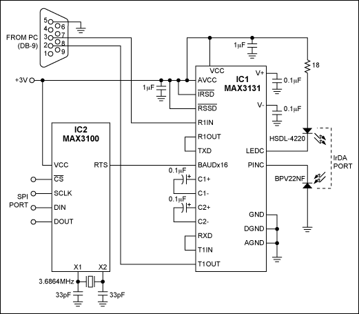
A specificaTIon defined by the Infrared Data Association (IrDA) in 1993 allows devices from different manufacturers to communicate without wires. IR ports are now available in various laptops, keyboards, PDAs, and calculators, but not in most desktop PCs. The two-IC circuit in Figure 1 permits a PC to communicate with other IR-port devices.

Figure 1. These two ICs enable a PC to communicate with a standard IrDA port.
IC1 includes two RS-232 transceivers, an IR transceiver, and one encoder/decoder (ENDEC). The connections shown enable it to convert from RS-232 to IrDA and vice versa. To compress standard NRZ signals into valid IrDA (RZ) signals and to stretch standard RZ IrDA back to standard NRZ, IC1 must be driven by a clock frequency 16 times the baud rate (baudx16).
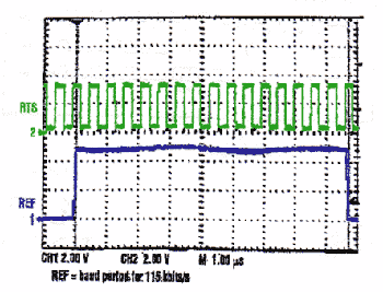
IC2 is a tiny hardware UART with a test mode that allows its use as an adjustable baudx16 clock generator. While in this test mode, the chip generates the baudx16 clock signal at its RTS terminal. Figure 2 illustrates the RTS signal for a baud rate of 115kbps. You don't have to synchronize this signal to the data stream; this task is accomplished within IC1. IC2 is SPI-compatible and capable of generating any baudx16 clock up to 3.6864MHz (which corresponds to a baud rate of 230.4kbps).

Figure 2. IC2 of Figure 1 generates this baudx16 clock (top trace) in response to a 115kbps baud rate.
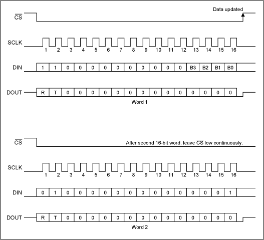
Using the SPI interface, you configure IC2's baudx16 test mode with two 16-bit digital words (Figure 3), in which bits B3-B30 are set according to a baud-rate selection table (see below). The two words set the baud rate for the baudx16 clock. They can be loaded with a programmable lab-data generator such as the Tektronix DG2020(A) or a low-cost microcontroller like the PIC16F84. The SPI port is used for this operation only once.

Figure 3. These 16-bit words configure IC2 (Figure 1) in its baudx16 test mode.
Baud-Rate Selector Table
Ratio
(fOSC =
1.8432MHz)
(fOSC =
3.6864MHz)
Notes:
Standard baud rates shown in bold
*Default baud rate
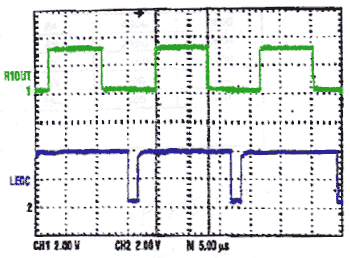
Figure 4 shows the conversion of standard NRZ logic signals (coming from IC1's TTL-compatible R1OUT terminal) to IrDA RZ logic signals at 115kbps. IC2 provides the baudx16 clock.

Figure 4. These waveforms show the Figure 1 circuit converting NRZ logic signals (top trace) to IrDA logic signals at 115kbps.
In an IrDA application, the three major layers required are the physical, protocol, and application layers. The circuit in Figure 1 completes the physical layer for IrDA serial infrared (SIR). Documentation for the protocol and application layers can be downloaded from the IrDA website. The protocol layer consists of the serial infrared link access protocol (IrLAP V.1.1) and the infrared link management protocol (IrLMP V.1.1). The application layer, which enables a standard serial port to support IrDA, is IrCOMM V.1.0.
A similar version of this article appeared in the February 21, 2000 issue of Electronic Design magazine.
欢迎分享,转载请注明来源:内存溢出

 微信扫一扫
微信扫一扫
 支付宝扫一扫
评论列表(0条)