High-Side Current Amplifier Forms 28V Circuit Breaker
Abstract: Using the MAX4373 high-side current-sense amplifier, a circuit can be designed with a voltage range to 28V. All that is needed is a general-purpose NPN transistor.
This design idea appeared in the June 1, 2006 issue of Power Electronics Technology magazine.
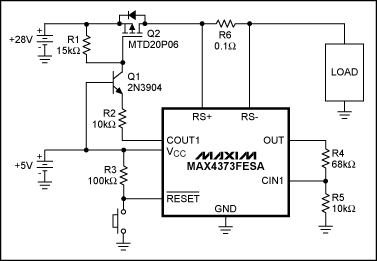
The latching-comparator output (COUT1) on the MAX4373, a high-side current-sense amplifier with comparator and reference, makes possible a circuit-breaker applicaTIon for that device (see Figure 2 of its data sheet). The data-sheet circuit, however, is suitable only for supply voltages in the range +2.7V to +5.5V. You can extend that range to 28V by adding a general-purpose NPN transistor, as shown in Figure 1.
Figure 1. The NPN transistor, Q1, extends the output swing of the comparator output, COUT1, in this circuit breaker.
The open-drain comparator output is driven low during normal operaTIon, allowing a nominal 430µA to flow from the transistor's emitter through R2 to COUT1. The same (approximate) current flows through the collector and R1, producing a VGS drive just over -6.4V for the p-Channel MOSFET.
The applicaTIon needs a circuit-breaker threshold of 900mA. The MAX4373FESA is chosen, because its gain from sense resistor to output is 50V/V. Thus, 900mA through the 100mΩ sense resistor, R6, drops 900mV, which is mulTIplied by the gain of 50 to yield 4.5V at the OUT terminal. The comparator's input threshold at CIN1 is 600mV, so a resistor-divider with ratio 6.5:1 is the target value. Choosing R4 at 68kΩ and R5 at 10kΩ yields an actual load-current threshold of 936mA, which is close enough for this application.
If the load current exceeds this threshold, the comparator output is latched into a high-impedance state. The transistor goes into cutoff and causes the MOSFET to turn off. Actuating the reset pushbutton restores the circuit to normal operation, provided that the fault has been removed.
This circuit topology works for applications in which the higher voltage (+28V in this example) is at least double the VCC voltage. Also, VCC is limited to +5.5V maximum to stay within the limits of the comparator's output. The unequal values for R1 and R2 in this circuit give a slight gain which, in turn, provides a bit more gate drive for minimizing losses due to the MOSFET's on-resistance.
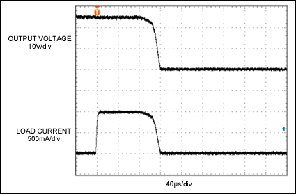
The circuit responds to an overcurrent condition in about 100µs (Figure 2). Its response (unlike that of a thermo-mechanical circuit breaker) is virtually unchanged for overcurrents only 10% above the threshold.
Figure 2. The load current shown (110% of the nominal 900mA threshold) trips the Figure 1 circuit breaker in about 100µs.
欢迎分享,转载请注明来源:内存溢出

 微信扫一扫
微信扫一扫
 支付宝扫一扫
评论列表(0条)