
要:本应用笔记说明了如何计算
DS31256 HDLC控制器的总线带宽。并展示了一个实验室实测的结果。同时演示了一个总线利用率速算表,该速算表如果需要可以索要。
概述DS31256 HDLC控制器通过PCI总线存取发送和收到的HDLC包。本应用笔记讨论如何计算DS31256正常工作所需的总线带宽。所涉及到的相关术语的定义在本文的开始部分给出。
根据本应用笔记所提供的信息,用户只需适当调整速算表(备索)中的一些数据,就可将它用于特定的应用中。
表1. 本应用笔记所涉及到的变量的定义
Variable
DefiniTIon
Valid Range
B
Average number of packets processed before the host updates the receive free queue and transmit pending queue or reads the receive done queue and transmit done queue
1, 2, 3, . . . .
C
Average number of bus cycles required per packet
1, 2, 3, . . . .
D
Number of bus cycles needed for data to be transferred
1, 2, 3, . . . .
P
Packet size in bytes
64
R
Average number of bus cycles added due to latency in RAM access
0, 1, 2, . . . .
X
Average number of bus accesses required to send or obtain packet data to, or from the data buffers
1, 2, 3, . . . .
总线访问类型DS31256或主机执行四种类型的总线访问,以支持DS31256内的直接
存储器访问(
DMA)。在下面的讨论中,变量D定义为数据周期数,变量R定义为由于RAM访问时间的关系,所需要的总线周期数。
访问类型1:DMA突发读主机RAM当DMA突发读主机RAM时所需要的总线周期总数为[3+R+D]。这可由图1和表2得出。
表2. DMA读所需的总线周期总数
Cycle
No. Cycles Required
Address Cycle
1
Turnaround Cycle
1
RAM Access Latency Cycle
R
Data Cycle
D
Turnaround Cycle
1
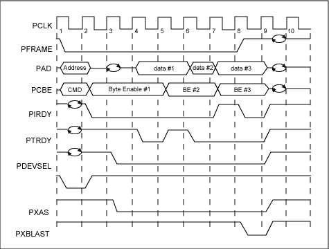
图1. DS31256 PCI总线读
访问类型2:DMA突发写主机RAM当DMA突发写主机RAM时所需的总线周期总数为[2+R+D]。这可从图2和表3得到。
表3. DMA写所需的总线周期总数
Cycle
No. Cycles Required
Address Cycle
1
RAM Access Latency Cycle
R
Data Cycle
D
Turnaround Cycle
1
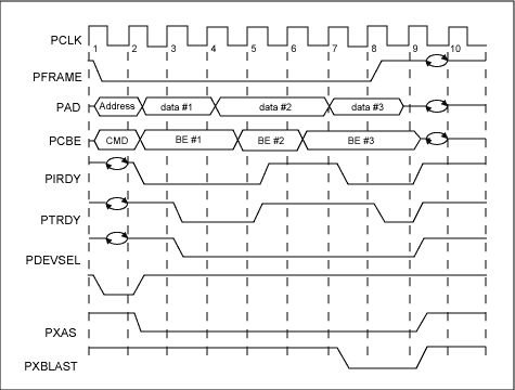
图2. DS31256 PCI总线写周期
访问类型3:主机写DS31256主机写入DS31256时所需的总线周期总数为7。
访问类型4:主机读DS31256主机读取DS31256时所需的总线周期总数为7。
注意:对于访问类型3和4,7个访问周期是DS31256所固有的,不能改变。
每个包所需的总线周期数为计算总线利用率,首先必须知道所需要的总线周期数。为得到该数据,我们做了一些假设列于表4。图3给出了在收到或发出一个数据包时主机和DMA将要执行的标准流程。根据图3,我们有可能得出一个公式,来计算每个包所需要的平均总线周期数,即变量C。
发送侧发送侧周期 = 读等待队列 + 写水平描述符链 + 读描述符 + 从主机存储器读取包 + 写完成队列 + 读/写
寄存器。
Ct = [(3 + R + 12)/12] + [2 + R + 1] + [3 + R + 4] + [(P/4) + (3 + R)X] + [(2 + R + 6)/6] + [4(7/B)]
接收侧接收侧周期 = 读自由队列 + 将包写入主机存储器 + 写描述符 + 写完成队列 + 读/写寄存器。
Cr = [(3 + R + 24)/12] + [(P/4) + (2 + R)X] + [2 + R + 3] + [(2 + R + 6)/6] + [4(7/B)]
总公式Ct + Cr = 21.16 + 3.5R + 0.5P + (5 + 2R)X + 56/B
表4. 为了便于计算每个包所需总线周期数所作的假设
1
All packets are 64 bytes (seen as worst case).
2
The Frame Check Sequence (FCS) of the HDLC packet is not transferred to, or from the PCI bus.
3
On the receive side, only large buffers are used (small buffers are disabled).
4
The receive DMA will burst read the free queue and burst write the done queue.
5
The transmit DMA will burst read the pending queue and burst write the done queue.
6
All packets fit within a single buffer (i.e., only one descriptor). This is reasonable because packets are 64 bytes.
7
All physical layer links are filled with packets; no idle codes are sent or received.
8
Interrupt rouTInes and overhead (like accesses to the local bus) are not considered.
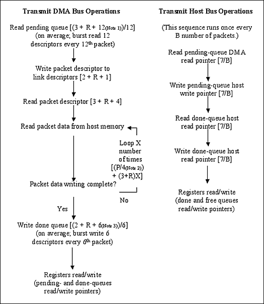
图3. 每个包的总线处理流程
注:
- 12个描述符 x 1双字 = 12个发送等待队列描述符双字
- 包数据字节数 = 4字节/数据周期
- 6个描述符 x 1双字 = 6个发送完成队列描述符双字
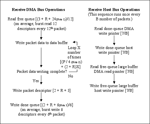
图3. (续)
注:
- 12个描述符 x 2双字 = 24个接收自由队列描述符双字
- 包数据字节数 = 4字节/数据周期
- 6个描述符 x 1双字 = 6个接收完成队列描述符双字
PCI总线利用率总线利用率定义为DS31256每秒所需的总线周期数除以每秒可供使用的总线周期总数。总线利用率可按照特定的HDLC配置和业务量计算。计算中假定PCI总线
时钟速率为33MHz (33,000,000Hz),并且只用一片DS31256。以下就是PCI总线利用率的详细计算方法。
公式1:

公式2:

注:
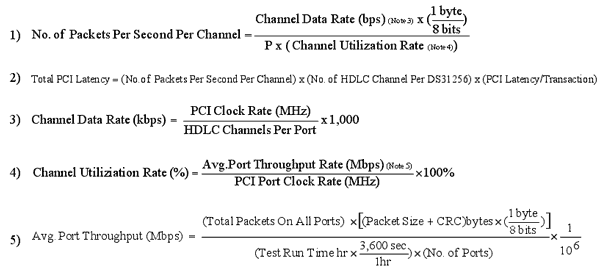
举例有关PCI总线利用率的实验室
测量结果展示了DS31256的PCI总线使用情况。其中假定所有收到的和发出的数据包都为56字节长(P = 56)。结果归纳于表5。我们还制作了一个可以计算总线利用率的速算表(如表6所示),如果需要可以索要(请联络
[email protected] (English only)。)
表5. PCI总线利用率实验室实测数据
B
P
R
Mode
No. of Ports
Avg. No. Done Queues Entries Processed
Pkt Size (Bytes)
Avg. RAM Access Latency Cycles
No. of HDLC Channels
Total No. of Channels
Channel Data Rate (kbps)
PCI Clock Rate (MHz)
PCI Bus UTIl.(%)
High Speed
3
14.17
56
8.35
1
3
52
52
47.55
Unchannelized
3
35.53
56
8.50
1
3
29
29
49.06
Low Speed
16
100.46
56
10.60
1
16
12
12
55.27
Unchannelized
16
24.30
56
10.24
1
16
10
10
52.54
T1
16
8.081
56
7.1375
12
192
128 *
1.544
18.26
E1
16
8.154
56
7.8645
16
256
128
2.048
28.07
2E1
16
10.894
56
8.003
16
256
256
4.096
55.82
4E1
16
381.207
56
8.3123
8
128
1024
8.192
50.97
* 注:
- 每个T1帧有193位 = [(24时隙 x 8位) + 1个同步位]
- 每个时隙的数据速率为64,000位/秒
- (64,000位/秒)/8位 = 8,000帧/秒
- 每125微妙到达一个T1帧 = 1/(8,000帧)/秒
- 数据速率为1,536,000位/秒 = 24信道 x (8位/信道/帧) x (8,000帧/秒)
- 线路总速率为1,544,000位/秒 = [(24信道 x (8位/信道)) + (1同步(位/帧))] x (8,000帧/秒)
表6. DS31256 PCI总线利用率速算表
Input Variables
B
14.17
The average number of packets processed before the host updates the Receive Free Queue and Transmit Pending Queue, or reads the Receive/Transmit Done Queues.
P
56
The size of the packet in bytes.
R
8.35
The average number of bus cycles added due to latency in RAM access.
Number of HDLC channels per DS31256
3
Use 1 per acTIve port when operating in unchannelized mode.
Channel Data Rate (kbps)
52,000.00
Note that T1 speed == 1536kbps.
Channel Utilization Rate
39.5%
There can be time between packets in real applications.
PCI Clock Rate (MHz)
33
PCI Latency/Transaction
10
This is based on the average number of cycles required to perform each of the transactions associated with processing a packet. Our designers use 10 in their simulations, which is fairly conservative.
Number of DS31256's on Bus
1
Intermediate Variables
C
104.04
The average number of bus cycles required per packet.
X
1.00
The average number of bus accesses required to send/obtain packet data to/from the data buffers.
Packets/second/channel
45,871.43
Total PCI Latency
1,376,142.86
No. of Bus cycles required/sec
15,693,122
Half Duplex
Full Duplex
Bus utilization
47.6%
95.11%
Bus Capacity (Mbps)
264
Bus Throughput (Mbps)
125.54
251.09
注:

其中,1024 blocks是F
IFO的尺寸,FIFO的高、低水印被设置于50%。
结束语本应用笔记解释了如何计算在给定应用中,DS31256对于总线带宽的要求。提供了一些实验室
测试的实例。并提供了一个可执行这种计算的
电子速算表,如果需要可以索取。


 微信扫一扫
微信扫一扫
 支付宝扫一扫
评论列表(0条)