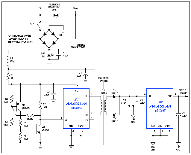

Figure 1. This circuit draws current in the off-hook condiTIon, delivering as much as 150mW of isolated power while allowing normal voice or data communicaTIons over the phone line.
The line current available to a telephone in the off-hook state is limited not by regulaTIons or code, but only by the sum of impedances in the central-office battery and intervening phone lines. These line impedances vary greatly (in proportion to distance from the central office), so the customary practice of matching impedances for maximum power transfer is impractical.
But, the zener-clamp termination (D1) works well for line impedances to 1000Ω and for worst-case conditions. It also meets the one condition imposed on line current by the phone system: off-hook current must exceed 20mA to ensure activation of a network-access relay in the central office.
D1 provides approximately 6.8V to the center tap of T1 and 5V to the VCC terminal of IC1. IC1—a 400kHz oscillator driving an internal flip-flop—generates two push-pull, 50%-duty-cycle, 200kHz square waves that drive internal, ground-referenced switches connected to the primary of T1. Isolated power on the secondary side is first rectified by Schottky diodes D2 and D3, and then regulated to 5V by the low-dropout linear regulator IC2.
T1's primary is a center-tapped winding whose ET product (a voltage-time product of 25V-µs) is sufficient to prevent saturation under worst-case conditions. Similarly, T1's turns ratio should provide the minimum-required output voltage for maximum load and minimum input voltage. This calculation should also assume worst-case losses in D2 and D3.
This turns ratio produces a much higher secondary voltage for best-case conditions, and for some applications that is acceptable. Otherwise, add the linear regulator (IC2) as shown. For isolated 5V outputs, the ideal turns ratio is 1.2CT:1.0CT (CT = Center Tapped). The transformer should be wound on Magnetics Incorporated "W," Fair-Rite "76," or other high-permeability magnetic material. To minimize radiated noise, choose a pot core, E/I/U core, toroid, or other geometry with closed magnetic paths.
Consider a typical toroid such as the 40603-TC from Magnetics, Inc. (0.125" thick with a 0.230" outside diameter). For 6.8V inputs this core should have a 48-turn primary (24 turns on either side of the CT), which yields a nominal, end-to-end primary inductance of 8mH. The secondary can be scaled for any reasonable output voltage required. Forty turns, for example, (20 turns on either side of the CT) delivers 5.2V minimum as required by the linear regulator for maintaining a regulated 5V output.
For isolated 3.3V applications, the minimum voltage to IC2 is 3.5V. T1's turns ratio should be 2.0CT:1.0CT, with a primary ET product of at least 25V-µs. Using the same 48-turn primary as for 5V applications, the required number of secondary turns is 24 (12 on either side of the CT). In addition, you must add a resistive divider for setting IC2's regulated output to 3.3V.
Q1, Q2, and the associated resistors assure a low-power shutdown mode for IC1 until its supply voltage can sustain a full power-up. IC1's supply current is fairly constant, so light filtering (provided by L1 and C3) is sufficient to prevent noise from entering the hybrid transformer (not shown).
A related idea appeared in the 9/1/94 issue of EDN.
欢迎分享,转载请注明来源:内存溢出

 微信扫一扫
微信扫一扫
 支付宝扫一扫
评论列表(0条)