This chip does not have a power-on-reset (POR) funcTIon. This application note demonstrates how to add this function, using one of the linear regulator controllers to reset the microprocessor 140ms after the output voltage is within the regulated output voltage.
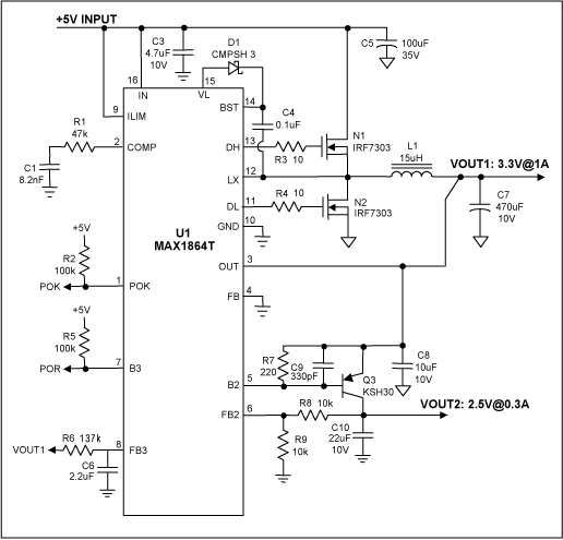
Figure 1 shows the circuit schematic. POR is used to monitor the main output, VOUT1. When the main output, VOUT1, reaches its specified output voltage, POR becomes active-high with 140ms delay. The synchronized buck and one positive regulator gain block (B2 and FB2) controller in the MAX1864 provide two outputs, while the second regulator gain block (B3 and FB3) monitors the main output voltage. A resistor, R6, is connected between the output, VOUT1 and FB3, and a capacitor, C6, is connected from the FB3 pin to ground. A pull-up resistor, R5, is connected to the supply voltage (+5V) through B3, and the output from B3 can be used as the POR output. When the output, VOUT1, is within the regulated range, the voltage at the FB3 pin gradually increases by charging the capacitor, C6, through the output, VOUT1. The voltage across C6 is dependent on the time constant of R6 and C6. With the values shown for R6 and C6, POR will become high 140ms after the time where the voltage at the FB3 pin is high enough.

Figure 1. Two output with POR function.
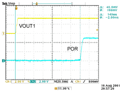
Figure 2 shows the POR and VOUT1 waveforms.

Figure 2. Experimental waveforms.
欢迎分享,转载请注明来源:内存溢出

 微信扫一扫
微信扫一扫
 支付宝扫一扫
评论列表(0条)