
The output voltage of an adjustable voltage reference, like the MAX6160, is set by the raTIo of two resistors, R1 and R2, in Figure 1. The relaTIonship between the voltage and the resistors is given by the equation next to the circuit in the figure. The equations for calculating the values for R1 and R2 are also shown.
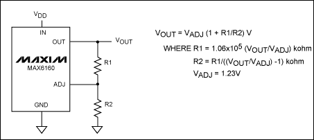
Figure 1. The MAX6160 adjustable output circuit with fixed precision resistors.
Coarse Adjustment over a Wide Voltage RangeFigure 2 combines the MAX6160 with the MAX5462 (a 100kΩ, 32-tap digital pot). This circuit is capable of digitally adjusting the output over the range from 1.23V to 5.3V. The ADJ pin voltage limits the minimum output voltage, and the supply voltage for the MAX5462 and the MAX6160 dropout voltage limit the maximum output voltage. This circuit is useful when the voltage reference needs to be programmed in the field to different levels and absolute accuracy is not critical but low drift is required.
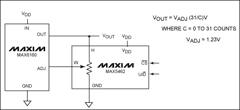
Figure 2. The MAX6160 digitally adjustable output circuit with the MAX5462 32-tap digital pot.
This circuit is capable of setting the output voltage to within 5% of 2.048V, 7% of 2.50V, 11% of 4.096V, and 16% of 5.00V. The key spec for the MAX5462 is the ratiometric resistance temperature coefficient (tempco) of 5ppm/°C. This low-drift characteristic enables drift performance comparable to a fixed output voltage reference with the flexibility to coarsely adjust the output.
The same topology can be used with the MAX5401 (a 100kΩ, 256-tap digital pot), shown in Figure 3, to increase the resolution by roughly an order of magnitude. This circuit is capable of setting the output voltage to within 0.6% of 2.048V, 0.8% of 2.50V, 1.3% of 4.096V, and 1.6% of 5.00V. It has the same benefits as the circuit in Figure 2 but with this increased resolution.
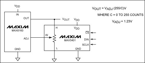
Figure 3. The MAX6160 digitally adjustable output circuit with the MAX5401 256-tap digital pot.
Fine Adjustment over a Narrow Voltage RangeThe circuit in Figure 4 uses the MAX5160 (a 32-tap digital pot) with two fixed precision resistors to finely tune around a specific output voltage. The tuning resolution is increased and the range is decreased as the ratio of the total fixed resistance to the digital pot resistance is increased. Table 1 shows the resistor-value selection optimized to achieve 0.5% tuning accuracy. These resistor values can be altered depending on the requirements for initial accuracy and drift.
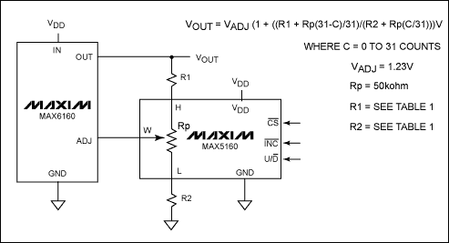
Figure 4. The MAX6160 digitally adjustable output circuit with the MAX5160 32-tap digital pot and fixed precision resistors.
Table 1. Resistor-Value Selection for the Figure 4 Circuit to Achieve 0.5% Accuracy
Fine Adjustment over a Wide Voltage Range Figure 5 combines the MAX6160 with the MAX5415 (a dual, 100kΩ, 256-tap digital pot) to achieve a fine adjustment over a wide output-voltage range. Due to the symmetry in this circuit, there is some redundancy, making only 25% of the settings unique. With this interesting topology, the output can be set to within 0.06% of 2.048V, 0.03% of 2.500V, 0.08% of 4.096V, and 0.2% of 5.00V. Because of the interaction between the two pots, the transfer function is nonlinear in two dimensions, resulting in a response that resembles a saddle. A plot of this is shown in Figure 6, where 32-tap digital pots are used instead of 256-tap digital pots for clarity.
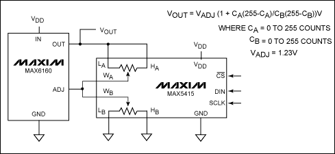
Figure 5. The MAX6160 digitally adjustable voltage reference with the MAX5415, dual, 100kΩ, 256-tap digital pot.
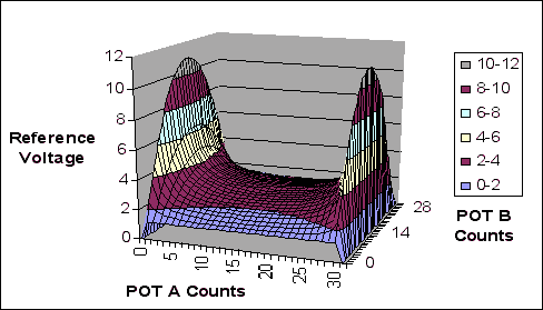
Figure 6. Plot of Figure 5 circuit of reference voltage output versus pot A and pot B (32-by-32 taps used instead of 256-by-256 taps for clarity).
SummaryThree circuit topologies were presented that provide the capability to digitally adjust the MAX6160's output voltage. The first topology provides the capability to coarsely adjust the output voltage over a wide range using a 32- or 256-tap digital pot. The second topology is capable of finely adjusting the output voltage about a single output voltage by using two fixed resistors and a 32-tap digital pot. The third topology can finely tune the output voltage over a wide range by using a dual, 256-tap digital pot. Table 2 summarizes the initial accuracy for each circuit presented.
Table 2. Summary of Initial Accuracy
32T, 100kΩ
256T, 100kΩ
32T, 50kΩ, Two Resistors
256T, 100kΩ, Dual
The initial accuracy, adjustment range, and long-term drift requirements for the system must be considered when choosing a circuit topology. The low wiper resistance, the low end-to-end resistor tempco, and the very low ratiometric tempco specifications make Maxim's digital potentiometers excellent choices to digitally adjust a reference voltage.
欢迎分享,转载请注明来源:内存溢出

 微信扫一扫
微信扫一扫
 支付宝扫一扫
评论列表(0条)