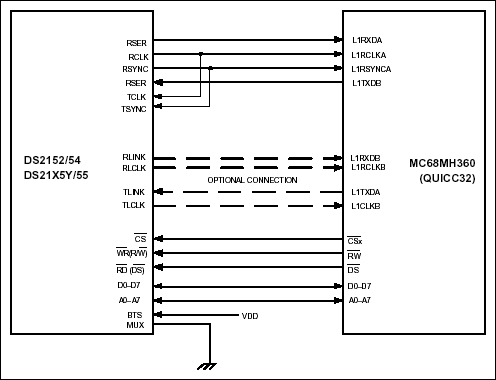
OverviewInterconnections between the DS2152, DS2154, DS21x5Y, or DS2155 and the Motorola MC68MH360 (QUICC32) are shown in Figure 1. The MC68MH360 can be configured as an HDLC controller implementing protocols such as LAPD for T1 FDL, DS0 channel SS7, or the E1 Sa bits.
However, the DS2152, DS21x52 and DS2155 have a built-in HDLC controller for the T1 FDL. Any combination of the QUICC32's SCCs and SMCs can be processed through an internal timeslot assignor onto one or two time-division multiplex channels, TDMA and TDMB. In the configuration shown, TDM channel A is used for timeslots 0 to 23 (T1) or 0 to 31 (E1), and TDM channel B is used optionally for the Sa bit (E1). Refer to the MC68360 Quad Integrated Communications Controller User's Manual for complete details.

Figure 1. DS2152, DS2154, DS21x5Y, or DS2155–QUICC32 Interconnections.
DS2152, DS2154, DS21x5Y, and DS2155 Notes:
- Other signals affecting operation of device are not shown.
- Example circuit has RSYNC in output mode.
- Other signals affecting operation of device are not shown.
- Use SI mode register t
- Set up transmit and receive frame-sync delays (0 to 3 clocks) to mask the F-bit in T1 applications.
- Set clock edges for transmit on rising edge and receive on falling edge. CEA = CEB = 0.
- In the above example, TDM channel A has a common transmit/receive clock and sync. CTRA = 1. Use the TIMESLOT ASSIGNER to ignore Timeslot 0 for E1 mode.
欢迎分享,转载请注明来源:内存溢出

 微信扫一扫
微信扫一扫
 支付宝扫一扫
评论列表(0条)