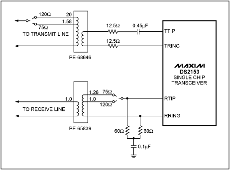
When interfacing to the E1 line with Secondary Over Voltage protecTIon or in a high return loss configuraTIon, resistors are added between the DS2153 outputs and the transformer. Normally the resistors are of different values depending on whether the interface is driving a 75Ω coax or 120Ω twisted wire pair line. Also a change in the termination resistor is required. A single set of resistors can be utilized in both situations by using the circuit shown in Figure 1. The dotted lines indicate jumper positions for selecting 75Ω or 120Ω operation.

Figure 1. E1 interface.
Table 1. Line Interface Control Register Settings
Notes:
- Transformers shown are available from Pulse.
- Resistors shown are within 1" of best value.
欢迎分享,转载请注明来源:内存溢出

 微信扫一扫
微信扫一扫
 支付宝扫一扫
评论列表(0条)